4237
Off-resonant excitation of frequency-adjustable magnetic field probes1Radiology - Medical Physics, Medical Center - University Hospital Freiburg, Freiburg, Germany
Synopsis
Manipulating the Larmor frequency of a frequency-adjustable 1H field probe provides interesting new possibilities to excite and record the probe’s signal. Here, we present first proof-of-concept experiments that demonstrate the feasibility of selective off-resonant excitation of the probe. Free induction decays with the applied resonance offset current were recorded and characterized.
Purpose
Magnetic field probes offer a great promise to improve MRI measurements.[1] Hydrogen-based field probes provide the highest signal but can interfere with the imaging process. Therefore, fluorine, deuterium or chemically-shifted field probes have been proposed.[2,3] This work presents selective off-resonant excitation of frequency-adjustable field probes.[4] This allows to use hydrogen-based field probes in cases where the commonly used fluorine-based field probes are impractical.Methods
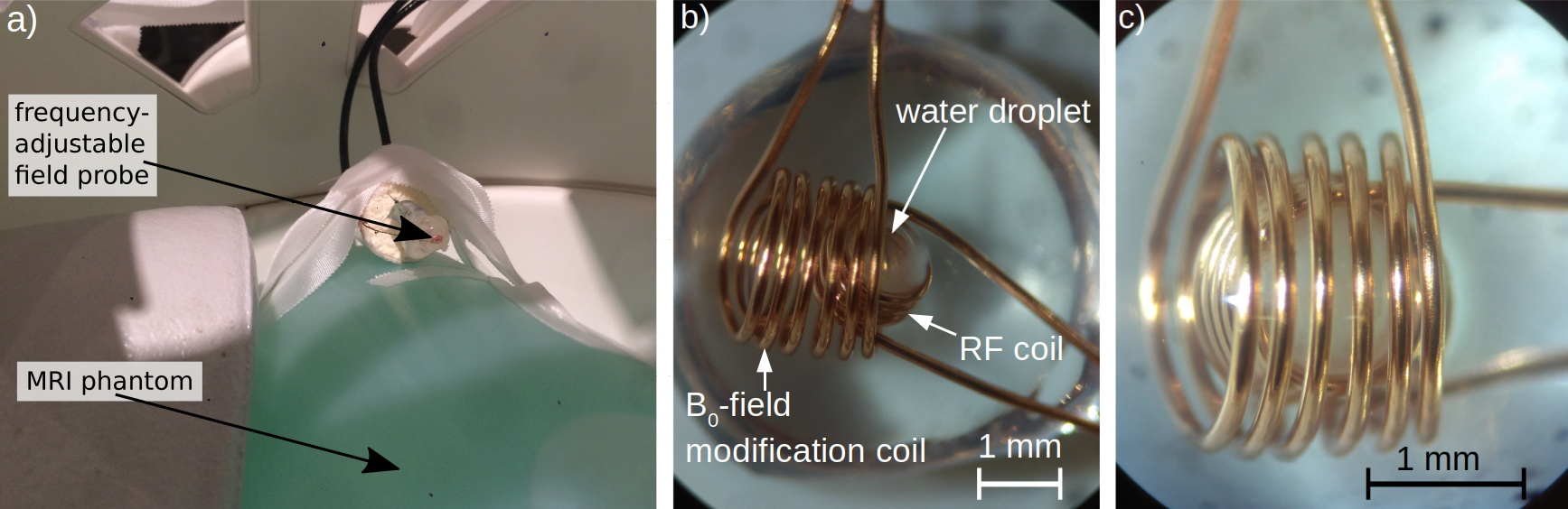
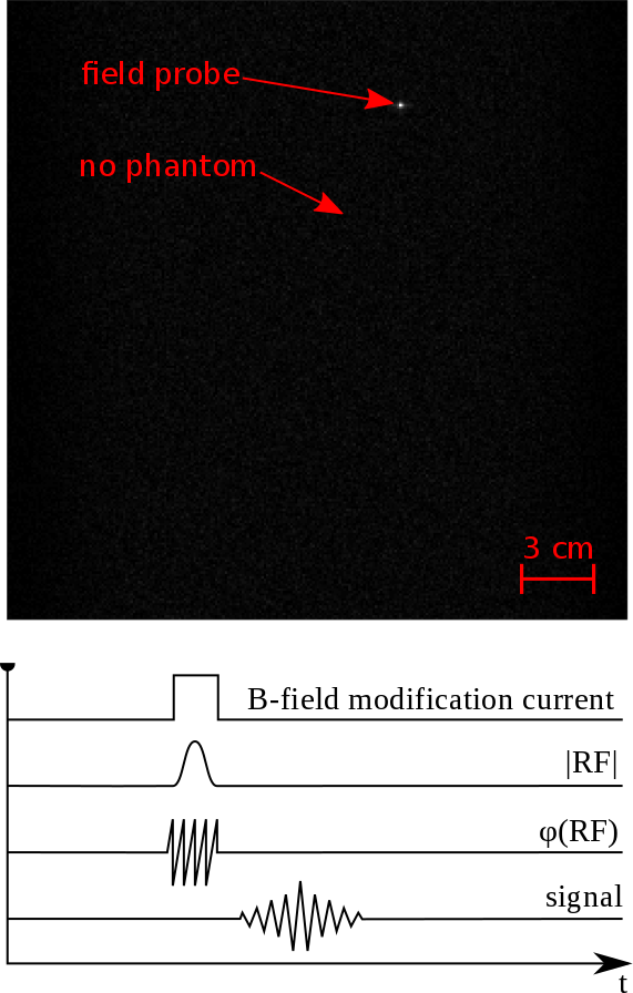
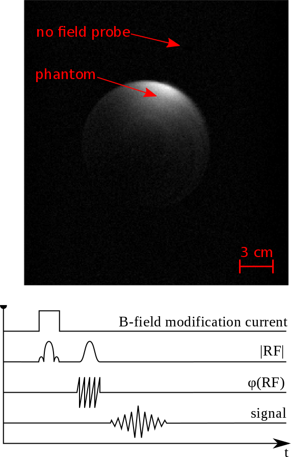
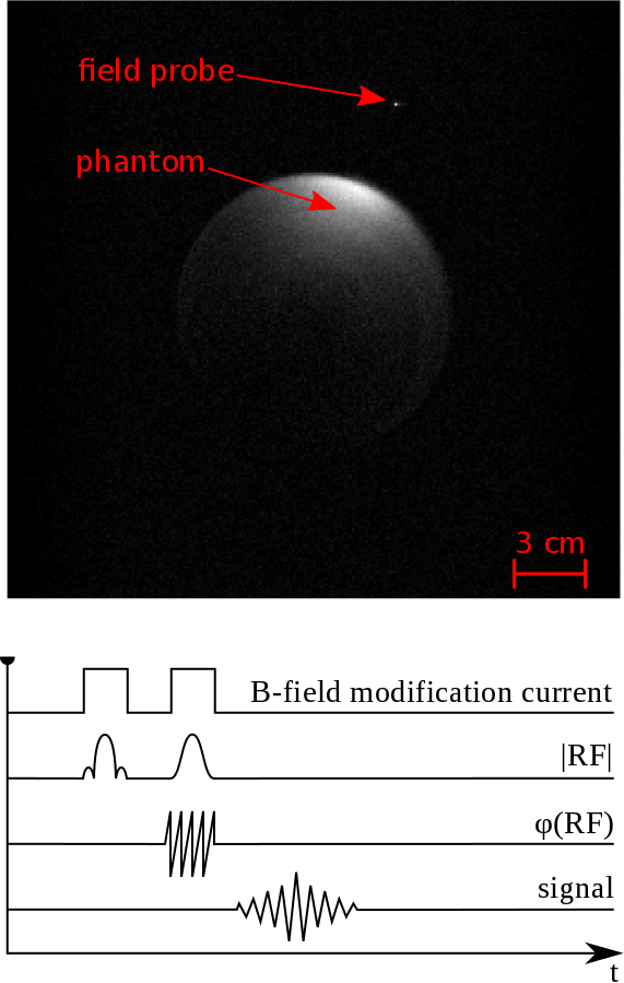
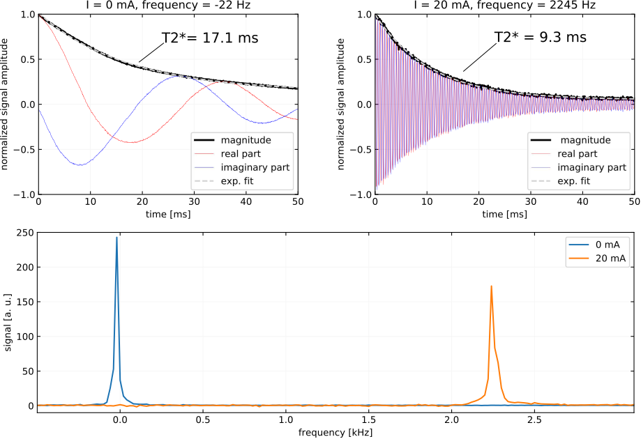
Frequency adjustable magnetic field probes were built as described in reference [4]. The resonance frequency of these field probes can be changed by running a current through its B0-field modification coil. MRI experiments were performed on a 3 T MAGNETOM PrismaFit system with a 20-channel head coil (Siemens Healthcare, Erlangen, Germany). Figure 1 shows the position of the phantom and the frequency-adjustable field probe. The RF coil of the probe was connected to the MRI system with a custom-built T/R switch and a low-noise preamplifier (Siemens Healthcare, Erlangen, Germany). The field probe’s RF coil was operated in the receive-only mode. The current in the B0-field modification coil of the field probe was controlled with a power supply located in the control room of the MRI system connected via a 7 m long coaxial cable. A choke balun and a low pass filter were used to suppress both RF coupling and external noise associated with the cable. The Pulseq framework [5] was applied to implement a custom gradient echo (GRE) sequence. Trigger signals were added to control the current in the B0-field modification coil. The MRI system supplied the trigger signals via an optical output, controlling a custom built trigger box that switched the current provided by the power supply on and off. A solenoid driver IC (ULN2003B, Texas Instruments, USA) was used as switch. The power supply was set to a current of 20 mA at a max. voltage of 20 V. Additionally, the GRE sequence was extended by using a Gaussian pulse for field probe excitation. The Gaussian pulse for probe excitation was set to the shifted resonance frequency of the field probe (i.e the frequency of the probe when the B0-field modification current is on). For measurement presented here, the frequency was shifted by +2265 Hz compared to the center frequency of the MRI system. The frequency encoding direction was in Z direction of the laboratory frame. Three pulse sequences were implemented to demonstrate the selective off-resonant excitation of the new field probe. The first sequence was implemented without main pulse and with the trigger turned on during the Gaussian pulse. In the second sequence the trigger was only turned on during the main pulse and was turned off during the Gaussian pulse. The third sequence had the trigger turned on for the duration of both the main and the Gaussian pulse. Corresponding schematic sequence diagrams are depicted in figures 2 - 4. In addition, free induction decays (FIDs) were recorded both after excitation at the main RF-frequency and after off-resonant excitation. This means the RF frequency offset was set to 0 Hz when no current was applied and to 2265 Hz during the measurement with a current of 20 mA. The FIDs were recorded with the receive coil of the field probe only. The MRI phantom was removed during these measurements in order to prevent interference with background signals in the recorded spectra.Results and Discussion
The GRE image in figure 2 shows a bright dot at the location of the field probe. In order to obtain a substantial signal from the probe, the excitation frequency has to be closely matched to the frequency shift induced by the B0-field modification coil of the field probe. After the frequency shift has been applied it is possible to hide the field probe from the excitation pulses as shown in figure 3. Figure 4 shows the case, when probe and phantom were excited by independent RF pulses and recorded simultaneously. The FIDs and the corresponding spectra at a modification current of 0 mA and 20 mA are depicted in Figure 5. At 0 mA B0-field modification current, the T2* of the field probe was 17.1 ms. Measured FIDs from the probe at 20 mA modification current and off-resonant excitation showed a shorter T2* of 9.3 ms at a frequency shift of 2.2 kHz. The reduction in T2* is probably caused by inhomogeneities on the B0-field of the used B0-field modification coil. The homogeneity of the relatively short solenoid coil used in the present proof-of-concept study is certainly not optimal. It can potentially be improved by additional wire windings and the optimization of the winding pitch. Alternative approach to improve the field homogeneity across the sample volume at the cost of SNR is to reduce the droplet size. Since the materials used to build the probe were not susceptibility matched, the T2* is relatively short compared to the probes presented in [1]. The manufacturing of susceptibility matched-prototypes is planned in near future.Conclusion
The selective off-resonant excitation of frequency-adjustable magnetic field probes was demonstrated. Findings can be beneficial in manifold ways leading to a more flexible measurement design and eventually allowing the integration of probes within the RF coils or the gradient bore.Acknowledgements
No acknowledgement found.References
1. Barmet et al. Spatiotemporal magnetic field monitoring for MR. Magn Reson Med 2008;60:187–197.
2. De Zanche et al. NMR Probes for Measuring Magnetic Fields. Magn Reson Med 2008;60:176-186.
3. Jorge J et al. Tracking discrete off-resonance markers. Magn Reson Med. 2018 Jan;79(1):160-171.
4. Wehkamp et al. Frequency adjustable magnetic field probes. ISMRM 2019 (Abstract 0923)
5. Layton et al. Pulseq: A rapid and hardware-independent pulse sequence prototyping framework. Magn Reson
Med 2017;77:1544-1552.
Figures