4236
Analysis of Peripheral Nerve Stimulation in Asymmetric Non-folded and Folded Head Gradient Coil Design1GE Global Research, Niskayuna, NY, United States
Synopsis
Head-only gradient coil is not only more power efficient than the whole body system for high quality MR neuroimaging, but also reduces risk of peripheral nerve stimulation. In this abstract we compared two different head-only transverse gradient coil designs -- a non-folded design and a patient-end folded design, pointed out that the current turns on the connection region of the folded design that close to human body is more efficient to induce electric field and eddy current than the non-folded design in the neck, shoulder, chest and back. A connection-region turn-constrained folded coil design confirmed the observation.
Introduction
High quality MR neuroimaging is important to advancing our understanding of the brain and to improve clinical diagnosis. Since the FOV needed for brain imaging is about 22cm to 24cm, which is much smaller than that required in whole-body applications, smaller and more efficient head-only gradient coils that are closer to the patient can be designed to produce higher quality images [1] with lower power requirements. The use of head-only gradients for advanced neuroimaging also reduces the risks of peripheral nerve stimulation (PNS) when compared to whole-body gradients, which is important especially at high gradient strengths and slew rates [1,2]. Although human studies have been done to compare PNS thresholds across different MRI systems, the impact of gradient coil design on PNS has not been thoroughly studied.Folded gradient coil design [1,3], that have conductors on, or across, the connection region usually leads to even lower inductance and higher efficiency compared to separate primary layer and shield layer coil designs (non-folded coil). However, the impact of these coil architecture choices on PNS performance is not well documented. Here, we compared the induced electric fields and eddy currents in a realistic human body model for non-folded and folded asymmetric head gradient designs.
Method
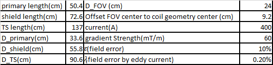
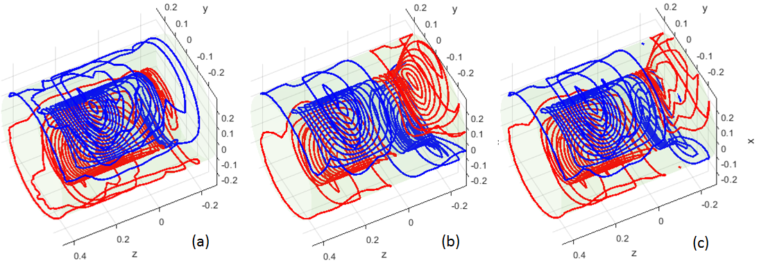
In this abstract, we only compared the x transverse coil design of the most efficient folded architecture (folded on the patient-end) to the non-folded architecture since x head gradient coil usually provides the lowest PNS threshold among the x,y,z coils. The dimensions and the specifications in our designs are similar to those in the reference paper [3] but simplified without loss of generality. They are summarized in Tab.1. A Boundary Element Method was used to find the optimal current distribution [4]. The wire patterns after quantization of the non-folded and folded designs can be found in Fig.1(a) and (b). After being normalized to $$$10 mT/m$$$ , the magnetic field ($$$\vec{B}$$$-field) and corresponding vector potential field ($$$\vec{A}$$$-field) of the designs were calculated directly by the Biot-Savart Law and used to calculate the electric field and eddy current distribution inside of the Duke human body model (IT'IS Foundation) under a 1000 Hz sine wave excitation with the commercially available Sim4Life software (Zurich MedTech, Switzerland). Duke model was positioned in the coils with whose glabella being about at the iso-center of the FOV.Results and Discussions
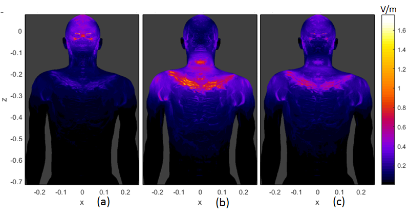
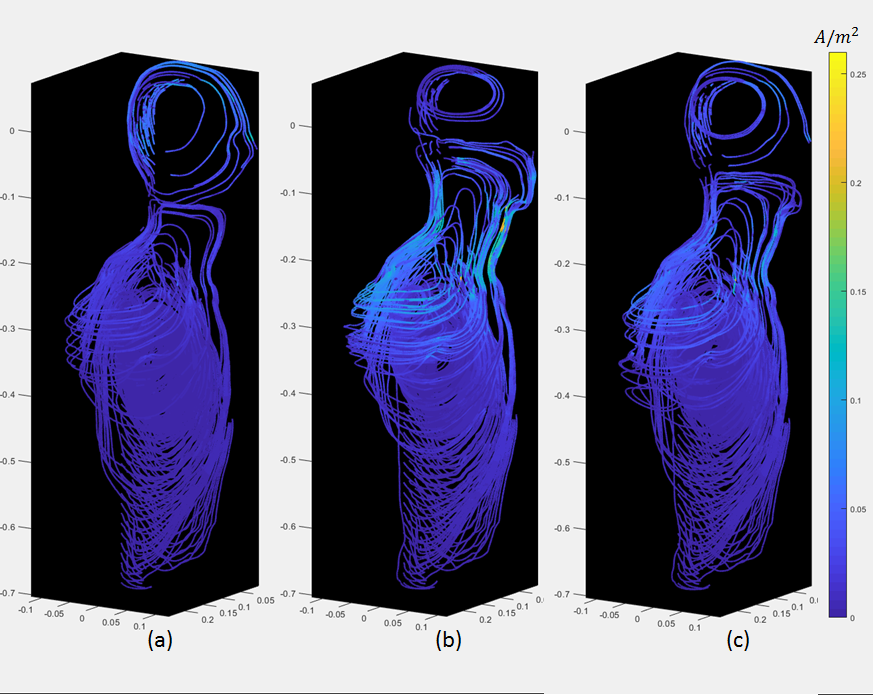
Fig. 2 (a) and (b) show the $$$|\vec{E}|$$$-fields of the non-folded and folded designs. For the voxels of same $$$(x,z)$$$ coordinates, only the maximum $$$|\vec{E}|$$$-value in $$$y$$$ direction in the model is shown. It is noted that $$$|\vec{E}|$$$ is higher in the glabellar region for non-folded architecture, but in the folded coil case, it is higher in the neck, shoulder, chest and back. Fig. 3(a) and (b) are the flow plots of the current density $$$\vec{J}$$$ in the Duke model for the two gradient architectures, the color shows its amplitude. Only the right half of the body is shown since the geometry is about left-right symmetric. The $$$\vec{E}$$$-fields in the bone, cartilage and cerebrospinal fluid were set to zero to avoid the non-interested high values [2,5], and the same rule was also applied to $$$\vec{J}$$$-flow plots. The $$$\vec{J}$$$-flow plots confirmed the $$$|\vec{E}|$$$-fields.It can be easily seen that there are current turns on the connection region (Fig.1(b)) between the primary and shield layer for the folded architecture. While these turns are efficiently contributing to establish the gradient field, they are also very close to the human body such that they can induce electric field and eddy currents in the body more easily. Under such circumstances, a 3rd design was performed to constrain the current density on the connection region of the folded architecture so that only half number of turns are in this region compared to the original folded design. The wire pattern of this design is shown in the Fig.1(c) and the amplitude of $$$\vec{E}$$$ and $$$\vec{J}$$$ are both reduced compared to the original folded case (refer to Fig.2(c) and Fig.3(c)).
Conclusions
For asymmetric x head gradient coil design, the current turns on the connection region of the patient-end folded coil are not only close to the FOV but also very close to patient body. They are efficient to contribute to gradient strength meanwhile can induce higher electric field and eddy current in the closeby region of human body. A design with reduced turn number in connection region confirms the observation. This information can be used to guide the high performance head gradient coil design for neuroimaging applications. Future work using a neuro stimulation simulation model will include an analysis of each design in terms of whether the regions with larger $$$|\vec{E}|$$$ or $$$|\vec{J}|$$$ are more likely to induce PNS [5].Acknowledgements
This work was funded in part by CDMRP W81XWH-16-2-0054.References
[1] Foo TKF, Laskaris E, Verilyea M, Xu M, Thompson P, Conte G, Van Epps C, Immer C, Lee SK, Tan ET, Graziani D, Mathieu JB, Hardy CJ, Schenck JF, Fiveland E, Stautner W, Ricci J, Piel J, Park K, Hua Y, Bai Y, Kagan A, Stanley D, Weavers PT, Gray E, Shu Y, Frick MA, Campeau N, Trzasko J, Huston J, Bernstein MA. Lightweight, Compact, and High Performance 3T MR System for Imaging the Brain and Extremities, Magn Reson Med. 2018; 80: 2232–2245
[2] Tan ET, Hua Y, Fiveland E, Vermilyea M, Piel J, Park K, Ho V, Foo TKF, Peripheral Nerve Stimulation Limits of a High Gradient Amplitude and Slew Rate Head-Gradient. Magn Reson Med, 2020;83:352–366
[3]Tang F, Liu F, Freschi F, Li Y, Repetto M, Giaccone L, Wang Y and Crozier S, An improved asymmetric gradient coil design for high-resolution MRI head imaging, Phys. Med. Biol. 2016; 61(24):8875-8889
[4] Poole M, Bowtell R, Novel Gradient Coils Designed Using a Boundary Element Method, Concepts in Magnetic Resonance Part B, 2007;31B(3)162-175
[5] Davids M, Guérin B, Vom Endt A, Schad LR, Wald LL, Prediction of peripheral nerve stimulation thresholds of MRI gradient coils using coupled electromagnetic and neurodynamic simulations. Magn Reson Med. 2019; 81(1):686-701
Figures