4231
MRI Room Placement: The effect of an elevator operation on local magnetic environment1The xMR Labs, Physics and Astronomy, Western University, London, ON, Canada, 2Medical Biophysics, Western University, London, ON, Canada
Synopsis
Developments in MR systems are allowing for siting which does not follow the typical “4 zone” architecture, removing barriers for MR implementation. A consequence of this is that these systems are nearer to elements of a building or hospital that may cause field distortions and cannot be resolved by shimming. This work quantifies the field distortions due to two typical elevators along a hallway and compares the distortion to a fit using a magnetic dipole approximation, verifying a 1/r3 field behaviour. This demonstrates the need for MR system placement guidelines which mitigate potential field stability concerns due to building elements.
Introduction
Developments in modern MR systems are allowing for more widely accessible systems that blur the lines of the typical “4 zone” MR room approach. This simplification can reduce costs associated with the set up of systems but comes at the expense of placing these sensitive systems nearer to objects which cause field distortions, potentially introducing challenges for applications which require high field stability. Of concern are the sources of field disturbance whose distortions are dynamic and cannot simply be resolved with shimming, such as an elevator, nearby car park, or the movement of a metal patient gurney. Studies to date on the magnetic fields generated by this class of objects focus more on applications for localization based on these distortions and their analysis is based on data collected using magnetometers with low precision1. In this paper, the field distortions due to typical elevators were investigated to gain insight into the potential effects on main magnetic fields of moving metal objects near an MR scanner.Methods
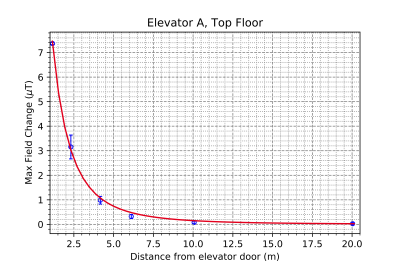
Field information was collected using a 3-axis fluxgate probe with calibration range 0-100 µT (Metrolab THM1186). The sampling rate of the probe was set to 100 points per second, and a 50-point rolling average was performed to reduce the noise in the measurements, also providing a standard deviation. Two elevators (Elevator A and Elevator B) were used in this study. A schematic of the probe locations measured is shown in the experimental setup Figure 1. A time series was acquired while the elevator was taken to each floor in order, producing a record of the field changes relative to the initiation of data collection (initial condition was door open while on the same floor as the probe). This process was repeated for all 6 positions on all the accessible floors for both elevators. The analysis of magnetic field time series was conducted in Python, with the maximum field change determined at each of the sampling locations. The maximum field change as a function of distance was fitted to a 1/r3 function to match a gross approximation of the elevators as magnetic dipoles2.Results
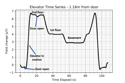
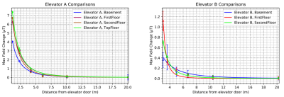
Figure 2 shows an annotated sample time series, highlighting the change of floors as the elevator cycles, as well as the confidence intervals due to the rolling average taken. The 1/r3 fit is shown in Figure 3 for the six positions on a particular floor for elevator A as an example. In Figure 4, all the data for both elevators, A and B, on all floors are shown with a fit, and in Figure 5 an order of magnitude comparison is shown for general distances from the elevator, with elevator B generally having lower field values at similar distances.Discussion
The expected fit showing the 1/r3 behaviour was verified, suggesting that in terms of modelling and predicting the effects that a system could be exposed to, a magnetic dipole approximation is appropriate. The limitations of this are evidently displayed in Figure 4 where the spread of the 50 point average leads to large error bars, particularly near the elevator door in B. Thus, it is recommended that for any modelling, the nearest predictions using a dipole approximation occur past 5m from the elevator door. In general, the effect on field was in the order of 1000 nT at ~5 m, 100 nT at ~10 m, and 10 nT at ~20 m. From this, it is unlikely that an elevator will significantly distort the static field of an MR system if located more that 10 m away. Typically, it is only the field oriented in the axis of the magnet that will affect imaging, and the current through the superconducting coils will flow to compensate for a changing magnetic flux. These factors represent a reduction in the effect of the distorting field of about an order of magnitude, with further work to be done quantifying these relationships.The elevators studied in this experiment both used a counterweight system. To expand the work, other elevator types such as freight and hydraulic systems could be tested. As well, other elements which can contribute to magnetic distortions exist in medical environments, and another step is to expand these measurements to other common sources of distortion in order to present a full picture of how the main magnetic field is affected. Modern approaches to field stability normally attempt to measure and compensate for or prevent distortion, such as using passive superconducting coils and passive steel room shielding. Developing guidelines for MR placement that account for some of these other factors could help to simplify the siting of an MR system.
Conclusion
In this work, we have conducted a study quantifying the effect that a typical elevator has on magnetic field in the vicinity. Through this study, these effects can be better quantified when determining the location of an MR system, particularly in relation to the moving elements in a building.Acknowledgements
The authors would like to acknowledge support form NSERC and the Ontario Research Fund.References
1. Shu Y, Bo C, Shen G, et al. Magicol: Indoor localization using pervasive magnetic field and opportunistic WiFi sensing. IEEE Journal on Selected Areas in Communications. 2015;33(7), 1443-1457.
2. Jackson J. D. Classical Electrodynamics, 1999.
Figures


