4226
Adaptive iPRES Body Coil Array with Microelectromechanical System Switches for Simultaneous Imaging and Localized B0 Shimming1Brain Imaging and Analysis Center, Duke University, Durham, NC, United States, 2Medical Physics Graduate Program, Duke University, Durham, NC, United States, 3GE Healthcare, Aurora, OH, United States
Synopsis
The adaptive iPRES(N) coil design can effectively shim localized B0 inhomogeneities, while requiring one power supply per RF coil element and 4 MEMS switch packages to direct the DC current among the shim loops. Here, this design is improved by using only one 6-channel MEMS switch package per RF coil element and a SPI-interface to control all of them, which requires minimal space and a few command lines. In vivo experiments with an adaptive iPRES(2) body coil array demonstrated that it can reduce B0 inhomogeneities and EPI distortions more effectively than an iPRES(1) coil array, without requiring additional power supplies.
Introduction:
Susceptibility differences at air/tissue/fat interfaces induce localized B0 inhomogeneities, which cause artifacts such as distortions in diffusion-weighted imaging, but which cannot be effectively shimmed with conventional spherical harmonic shim coils. The integrated parallel reception, excitation, and shimming (iPRES) coil design allows RF and DC currents to flow on the same coil elements, enabling simultaneous imaging and localized B0 shimming with a single coil array1,2. For body imaging, the iPRES(N) coil design splits each RF coil element into N smaller shim loops with independent DC currents, enabling the shimming of highly localized B0 inhomogeneities3. However, it requires one DC power supply per shim loop, which significantly increases the cost and complexity (e.g., cable routing) of the system.In contrast, the novel adaptive iPRES(N) (iPRES(N)-A) coil design only uses one power supply per RF coil element and microelectromechanical system (MEMS) switches to adaptively direct the DC current flow among the N shim loops, as needed for shimming4. This design thus retains the ability of the iPRES(N) design to shim highly localized B0 inhomogeneities, while maintaining the same number of power supplies (and a similar cost and complexity) as that of the iPRES(1) design. Its feasibility was demonstrated in proof-of-concept phantom experiments using a single iPRES(2)-A coil with four 1-cm2 MEMS switch packages4. Additionally, simulations with an 8-channel iPRES(4)-A body coil array showed that its shimming performance in the abdomen was comparable to that of an iPRES(4) coil array, while only requiring 8 instead of 32 power supplies4.
Here, we improve the original iPRES(N)-A design by using only one small (6x6-mm2) 6-channel, single-pole, single-throw MEMS switch package per RF coil element. All switches are controlled by a Serial Peripheral Interface (SPI) synchronous bus, which requires minimal space and only a few command lines for integration. We further integrate this new design into a 32-channel body coil array and perform in vivo shimming experiments to demonstrate that it can achieve an effective, yet affordable, localized B0 shimming for abdominal imaging.
Methods
iPRES(2)-A coil implementation:In this preliminary work, we implemented iPRES(2)-A into eight RF coil elements of the body coil array. Each coil element was modified by adding (Fig.1a): 1) interior DC traces and inductors (L1) to create two RF-isolated shim loops; 2) inductors (L2) to bypass the capacitors and allow a DC current to flow; 3) an external DC power supply line (DC+/DC-) with inductive chokes (Lchoke) to provide RF-isolation; 4) a MEMS switch package (Menlo Micro MM3100) placed on a printed circuit board (PCB) to direct the DC current into one or two shim loops, as needed for shimming, using one out of four possible configurations, or states, of iPRES(2)-A shim loops (Fig.1b-c); 5) two external 75-V and 5-V bias supply lines to turn the MEMS switch on; and 6) a micro-controller (Microchip Technology) mounted on the PCB within the scanner to send 8-bit serial logical commands (Fig.1e) to simultaneously turn the MEMS switch channels on/off and set the iPRES(2)-A states needed for shimming.
In vivo shimming experiment:
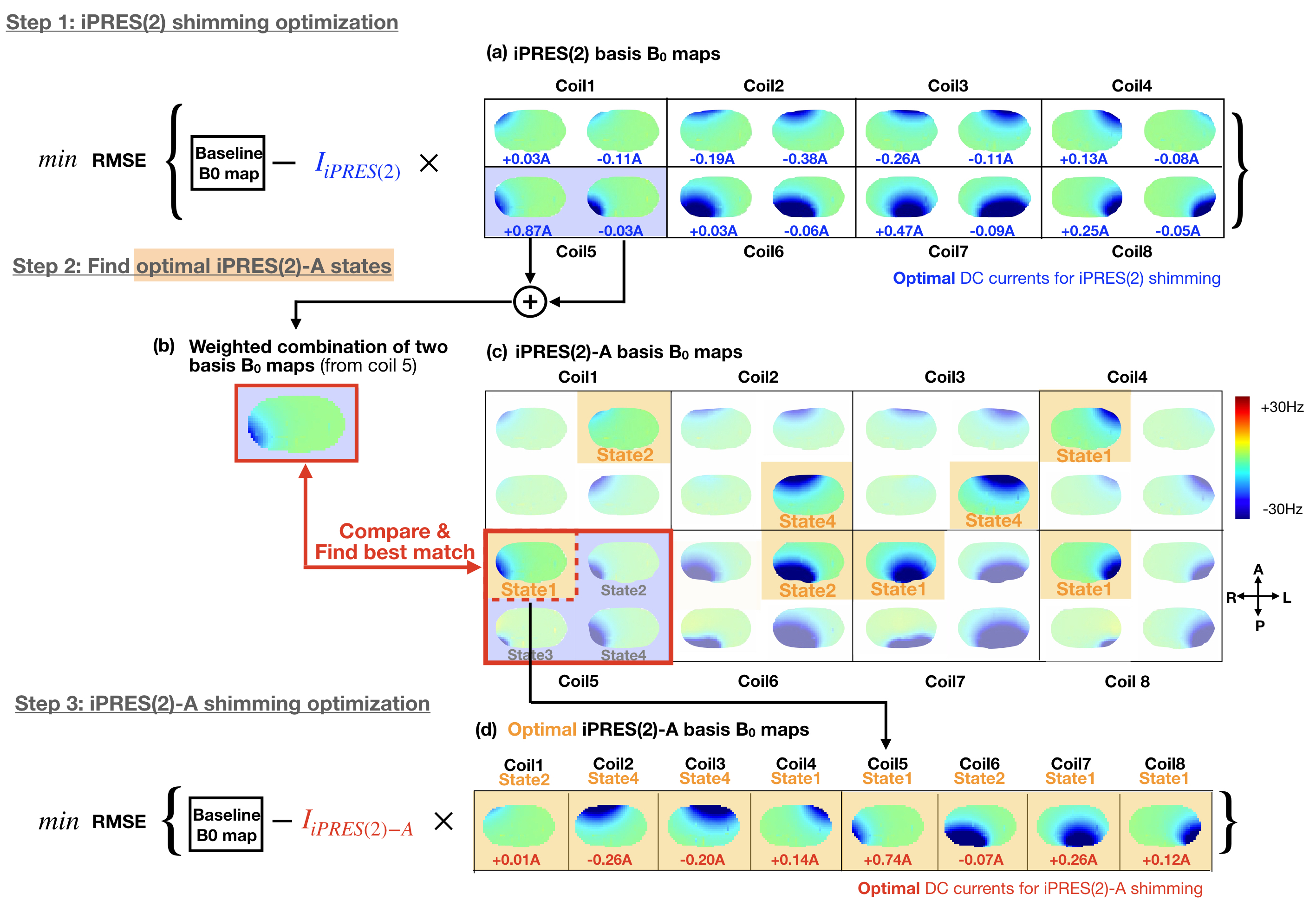
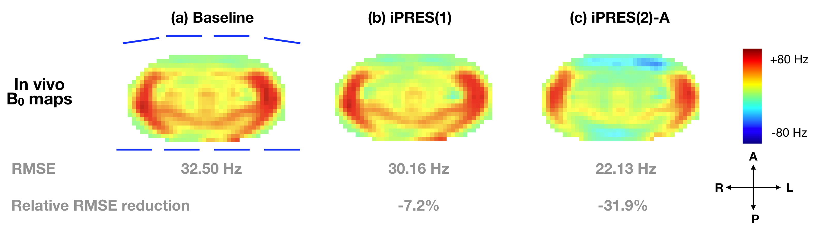
Thirty-two iPRES(2)-A basis B0 maps (Fig.2c) were acquired on a phantom with a DC current of 1 A separately applied to each state of each coil element. Sixteen of these B0 maps (states 1 and 2) correspond to the iPRES(2) basis B0 maps (Fig.2a), whereas eight of them (state 4) correspond to the iPRES(1) basis B0 maps. A baseline B0 map (Fig.3a) was then acquired in the abdomen of a healthy volunteer after linear shimming. An optimization4 was performed to determine the optimal DC currents and MEMS switch states for iPRES(2)-A shimming (as described in Fig.2). For comparison, another optimization was performed to determine the optimal DC currents for iPRES(1) shimming by minimizing the RMSE between the baseline B0 map and a combination of the iPRES(1) basis B0 maps. B0 maps and EPI images were acquired at 3T without vs. with the optimal iPRES(2)-A or iPRES(1) DC currents to evaluate the shimming performance of the iPRES(2)-A coil array. For iPRES(1) shimming, all MEMS switches were set to state 4.
Results
The in vivo B0 maps (Fig.3) and EPI images (Fig.4) show that the iPRES(2)-A coil array can greatly reduce the localized B0 inhomogeneities in the abdomen and effectively correct for the resulting EPI distortions compared to the baseline or iPRES(1). Residual B0 inhomogeneities and distortions, particularly in the lateral regions, which were further away from the coil elements, may be addressed by wrapping the coil array closer to the body and/or by implementing iPRES(2)-A in the remaining 24 RF coil elements.Discussion and Conclusion
In this work, we proposed an innovative iPRES(2)-A coil design that only uses one small 6-channel MEMS switch package per RF coil element along with an SPI bus to efficiently control all MEMS switches. We integrated this design into a body coil array and experimentally demonstrated its ability to shim localized B0 inhomogeneities more effectively than an equivalent iPRES(1) coil array, without requiring additional DC power supplies. This novel iPRES(N)-A coil design is expected to enable broader adoption of the iPRES technology to improve the image quality of body imaging techniques that are sensitive to B0 inhomogeneities (e.g., diffusion-weighted imaging), thereby benefiting many clinical applications.Acknowledgements
Acknowledgments: This work was in part supported by grants R21 EB024121, R01 NS075017, and R01 EB028644 from the National Institutes of Health, GE Healthcare, and the Duke-Coulter Translational Partnership. We thank Menlo Micro for providing technical support.References
[1] Truong TK, Darnell D, Song AW. Integrated RF/shim coil array for parallel reception and localized B0shimming in the human brain. NeuroImage. 2014;103:235-40.
[2] Stockmann JP, Witzel T, Keil B, Polimeni JR, Mareyam A, LaPierre C, Setsompop K, Wald LL. A 32‐channel combined RF and B0shim array for 3T brain imaging. Magn Reson Med. 2016;75(1):441-51.
[3] Darnell D, Truong TK, Song AW. Integrated parallel reception, excitation, and shimming (iPRES) with multiple shim loops per radio‐frequency coil element for improved B0shimming. Magn Reson Med. 2017;77(5):2077-86.
[4] Darnell D, Ma Y, Wang H, Robb F, Song AW, Truong TK. Adaptive integrated parallel reception, excitation, and shimming (iPRES‐A) with microelectromechanical systems switches. Magn Reson Med. 2018;80(1):371-9.
[5] Reeder SB, Wen Z, Yu H, Pineda AR, Gold GE, Markl M, Pelc NJ. Multicoil Dixon chemical species separation with an iterative least‐squares estimation method. Magn Reson Med. 2004;51:35-45.
Figures