4217
Power Control for an MRI Ablation Hybrid System1Otto-von-Guericke University Magdeburg, Magdeburg, Germany
Synopsis
Connecting an ablation electrode directly to the coil port of the MR
Introduction
The connection of an ablation electrode to the coil port of an MR scanner enables access to the power provided from the MR scanner's radio frequency (RF) amplifier. By using imaging sequences with a high duty cycle, an average power can be acquired, which is sufficient to perform thermal ablation1. This would make an external ablation generator obsolete, which can emit interferences for MR imaging2.Previous ablation experiments with the MRI ablation hybrid system were characterized by ablation at constant power. However, the formation of temperatures above 100 °C leads to carbonization of tissue, which can impair the ablation performance. Therefore, the temperature development must be limited by controlling the RF power during ablation.
In this paper, a proof-of-concept is presented to enable power control for RF ablation with an MRI ablation hybrid system using a scanner-remote control interface.
Methods
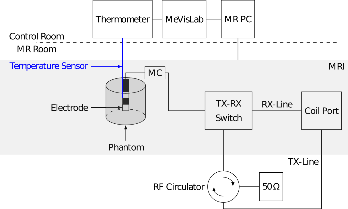
The test setup, shown in Figure 1, included the MRI ablation hybrid system and a periphery which enabled the implementation of a power control algorithm.Experiments were carried out in a 3T-MRI scanner (Skyra, Siemens Healthineers, Erlangen). The bipolar electrode was made from a semi-rigid coaxial cable (EZ-86-CU-TP-M17, Huber+Suhner, Herisau), and it was positioned inside a protein phantom3. The proteins inside the phantom denature at temperatures above 51 °C, which can be seen as a visible white opacification. A matching circuit (MC) was attached to the electrode to normalize the impedance of the electrode-phantom setup to 50 Ohm. The electrode was then connected to a transmission (TX)-receive (RX) switch, which allowed the electrode to operate as an imaging coil. Due to the temperature dependence of the dielectric properties, power reflections occurred during the procedure, which can damage the MR scanner. Therefore, an RF circulator was included in the TX path to attenuate the reflected power with a 50 Ohm resistor. A glass fiber temperature sensor (Fotemp, OPTOcon AG, Dresden) was placed next to the electrode tip to measure the temperature development during the thermal procedure.
When the electrode was connected to the coil port, turbo spin echo (TSE) sequences were executed to use the power from the MR-internal RF amplifier for ablation. The TSE sequences had the following settings: TR = 1460 ms, TE = 12 ms, turbo factor = 84, RF pulse type = "fast", averages = 8. The duration of one TSE sequence was 38 s. The total time of the heating experiment was 1100 s.
The RF power of the TSE sequence can be varied by changing the flip angle. For this purpose, the SIEMENS scanner remote control (SRC) interface was integrated into the medical prototyping environment MeVisLab [4]. Using the SRC interface, it is possible to enable live access to the MR scanner and request the host control to change the flip angle of the TSE sequence. In combination with the support of Python scripting in MeVisLab, an automated control algorithm was implemented to change the flip angle as a function of the temperature measured from the glass fiber sensor.
Aim of the experiment was to maintain a temperature between 80 °C - 90 °C during ablation. If the temperature was below 80 °C after ending the imaging sequence, then the flip angle should be increased by 10 °. If the temperature exceeded 90 °C during the imaging sequence, then the flip angle should be decreased by 10 °.
After the ablation, the protein phantom was cut, and the maximum extension of the visible thermal damage was measured.
Results
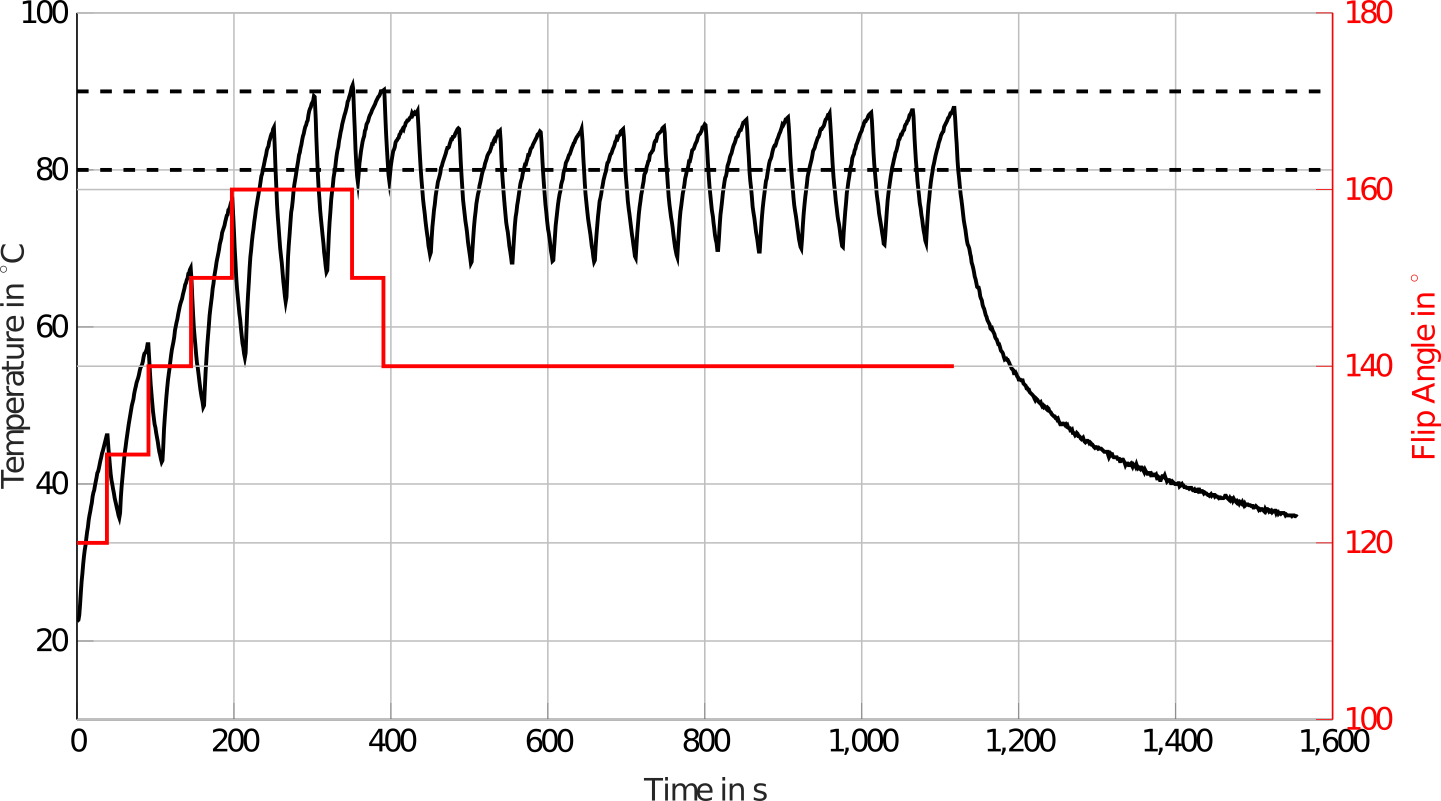
The temperature development displayed in Figure 2 shows a sawtooth behavior. During the execution of the TSE sequences, the temperature rises at the electrode tip, whereas the temperature falls between the end of a TSE sequence and the start of the next TSE sequence.The flip angle increases iteratively by 10° after each TSE sequence until a temperature of 80 °C is reached, which happened at t = 230 s. For the next three TSE sequences, the flip angle remains constant. However, the temperature exceeds 90 °C at t = 350 s. According to the implemented control algorithm, the flip angle is reduced iteratively by 10 ° until no temperature development above 90 °C occurs. From t = 450 s until the end of the ablation process, the ablation takes place at a constant flip angle of 140 °.
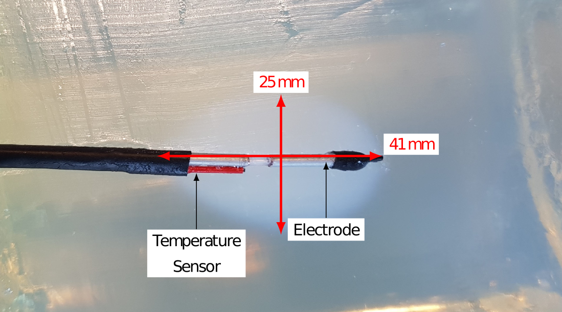
Figure 3 shows the denatured protein phantom after ablation. The size of the visible white opacification has an extension of 25 mm transverse and 41 mm longitudinal with respect to the electrode. The phantom shows no signs of charring.
Conclusion
It was shown that the SRC interface can be used to control the RF power for an MRI ablation hybrid system. This avoids carbonization due to temperatures above 100 °C near the electrode. However, the previous dead time between the end of a TSE sequence and the start of the next TSE sequence must be reduced in order to improve the ablation performance.Acknowledgements
This work was supported by the ESF within the context of the International Graduate School MEMoRIAL at the Otto-vonGuericke University (OvGU) Magdeburg, Germany (project no. ZS/2016/08/80646) and by the BMBF as part of the Magdeburg Research Campus STIMULATE (project no. 13GW0095A).References
1. Gerlach T, Pannicke E, Prier M, et al. Setup of an Ablation Magnetic Resonance Imaging Hybrid System: Using MR Imaging Sequences to Destroy Tissue. Conf Proc IEEE Eng Med Biol Soc. 2019
2. Will K, Krug J, Jungnickel F, et al. MR-Compatible RF Ablation System for Online Treatment Monitoring Using MR Thermometry. Conf Proc IEEE Eng Med Biol Soc. 2019
3. Bu-Lin Z, Bing H, Sheng-Li K, et al. A Polyacrylamide Gel Phantom for Radiofrequency Ablation. Int J Hyperthermia. 2008; 24(7):568-576.
4. Ritter F, Boskamp T, Homeyer A, et al. Medical Image Analysis. IEEE Pulse. 2011; 2(6):60-70.
Figures