4214
Proposed Calibration of the Torsional Spring in Torque Measurement Method Described in ASTM F2213-17
Xiao Fan Ding1, William Handler1, Dereck Gignac1, and Blaine Chronik1
1The xMR Labs, Department Physics and Astronomy, Western University, London, ON, Canada
1The xMR Labs, Department Physics and Astronomy, Western University, London, ON, Canada
Synopsis
The procedure for the 'Torsional Spring Method' from the internationally recognized standard on measuring induced torque on medical implants, ASTM F2213-17, leaves out information regarding the calibrating and quantifying of the spring constant which is crucial for its use in calculating torque. This abstract is a proposed method for the purpose of calibrating a torsion balance to enhance the utility of this internationally recognized test standard.
Introduction
The safety of commercial medical devices in the MR environment is regulated by several internationally recognized test standards [1]. One of which, ASTM F2213-17, is the standard on static field induced torque on medical devices when placed in the magnetically uniform region of the MRI scanner. Of the five methods described for evaluating torque, three are pass/fail criteria and two include quantitative measurements [2]. The ‘Torsional Spring Method’ which is one of the two methods for measuring induced torque (see Figure 1) relies on a platform suspended above and below by nylon threads under tension, with the tension being adjustable.The method outlined in the standard consists of the following: All around a holding platform are angular markings with a minimum resolution of 1°, to denote the angular position as the platform rotates. The device is fixed to the platform and when the system comes to equilibrium outside of the scanner, that position is marked and referenced as the zero-torque position. The apparatus with device fixed is then placed into the scanner and positioned such that the device is at the magnetic isocenter where the field most uniform. The platform-spring system is rotated in intervals of 10°, a torque induced angular deflection occurs and is measured. It is recommended that the deflection, Δθ, be no more than 25°. The product of the greatest deflection and the torsional spring constant, k, is used to calculate the greatest torque induced on the device.
$$\tau=k\Delta\theta$$The uncertainty, δτ, is propagated by the spring constant and its uncertainty, k and δk, and the deflection angle and its uncertainty, Δθ and δθ.
$$\delta_\tau=(k\Delta\theta)\sqrt{\left(\frac{\delta_k}k\right)^2+2\left(\frac{\delta_\theta}{\Delta\theta}\right)^2} $$To effectively use this method, the spring needs to be calibrated to quantify the spring constant. In addition, due to the 25° deflection limit, the springs need to be adjusted an appropriate spring constant. The latest version of the standard does not include a method for calibration or quantifying the spring constants of the torsional springs, which is necessary for its use and calculating the torque. What follows is a proposed calibration schema for this calibration, making measurements with this system viable.
Methods
The following outlines a proposed method for calibrating the torsional springs by using standard masses and relies on the constructed apparatus shown in Figure 2 as a reference.Around the holding platform, there needs to be a groove so that a thread can be wound. The thread is connected to a weight holder into which, well-known pre-defined standard masses can be placed. The advantage to using standard masses is that it eliminates the need for yet another measurement. The thread is then placed over a low-friction pulley so that the torque applied from the weight of the mass creates a deflection in the holding platform. The torque from the mass is the product of the radius of the platform and the weight of the mass used, τ=mgr, which in turn can be used to quantify the spring constant from the measured deflection because τ=kΔθ so therefore, kΔθ=mgr. With a desired spring constant in mind, the angular deflection that would occur from the mass used is calculated and the platform-spring system is adjusted until the approximate angular position is achieved. Once the desired spring constant has been calibrated, the aforementioned ASTM published procedure can be performed for torque measurements. An estimate of the accuracy in the calibration of four spring constants, 0.3, 0.9, 1.5, and 2.1 mNm, were calculated.
Results
Figure 3 shows the calculations made for four calibrated spring constants. These values were used to propagate the absolute and relative instrument uncertainties of the torsional spring method shown in Figure 4 and Figure 5 respectively.Discussion and Conclusion
The torsional spring method is restrictive method given the 25° deflection limit. It is made even more cumbersome to use as the standard lacks crucial information such as what kind of springs to use or how the spring constant should be quantified. However, the proposed calibration schema for the springs makes this method more useful in that it can be dynamically calibrated for whatever range of torque measurements. It would be even better if the ability to calibrate the springs was built into apparatus.Appropriate use depends upon choosing the right spring constant for your measurement, which depends upon the size of the torque being measured. For small torques a large spring constant results in a large error, so the spring constant would need to be reduced.
The torsional spring method, in spite of present limitations, can be used for a variety of devices by the calibration of the springs. However, as of the most recent version of the standard, there does not exist a standard method for such a task. Furthermore, the standard does not mention of the appropriate type of springs used or a method for quantifying the spring constant. This work describes a proposed calibration method for quantifying the spring constant and enhance the utility of an internationally recognized test standard.
Acknowledgements
The authors would like to acknowledge The Ontario Research Fund, NSERC, and the Canadian Foundation for Innovation.References
- Woods, T. O. (2007). Standards for Medical Devices in MRI : Present and Future. Journal of Magnetic Resonance Imaging, 26, 1186–1189. https://doi.org/10.1002/jmri.21140
- ASTM International. (2017). Standard Test Method for Measurement of Magnetically Induced Torque on Medical Devices in the Magnetic Resonance Environment.
- Pavlis, N. K., Holmes, S. A., Kenyon, S. C., & Factor, J. K. (2013). Erratum: Correction to the development and evaluation of the earth gravitational model 2008 (EGM2008). Journal of Geophysical Research: Solid Earth, 118(5), 2633.
Figures
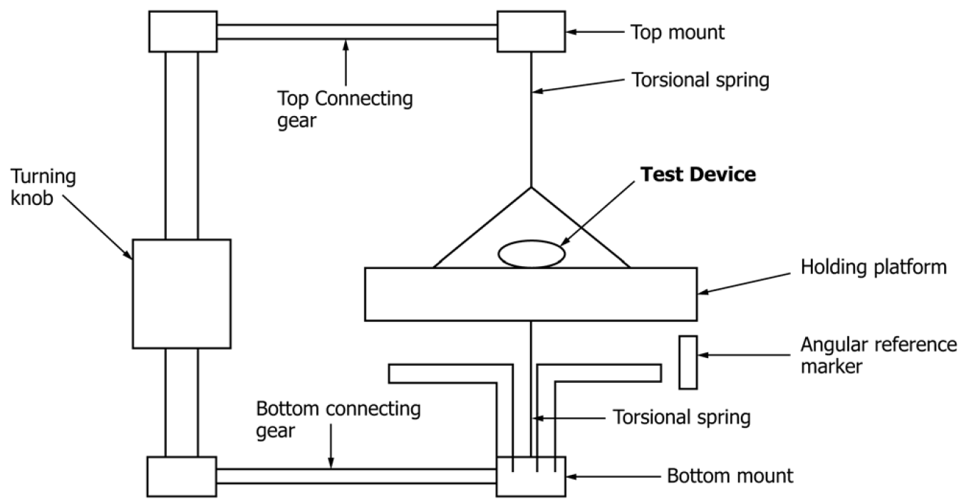
Figure 1: Schematic diagram of the torsional
spring method apparatus. The top and bottom connecting gears allow for the
system of torsional springs and platform to rotate as a single unit. As this
system rotates, the torque induced on the test device to orient with the static
field which results in a measurable angular deflection. Retrieved from ASTM
F2213-17.
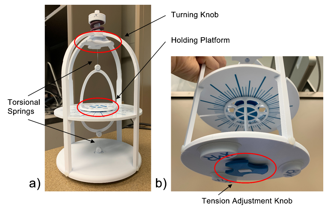
Figure 2: a) front view b) bottom view of a
torsional spring apparatus based on ASTM specifications shown in Figure 1.
The torsional springs in this apparatus are nylon threads stretched under
tension. The tension in the threads can be adjusted by a knob on the bottom.
The knob above is intended to rotate the spring-platform system, a method
differing from the connecting gears in Figure 1.
Angular demarcations and reference marker were incorporated into the design.
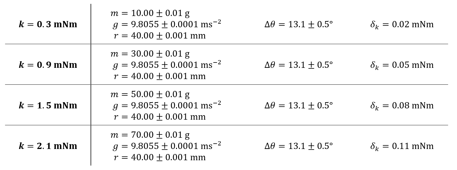
Figure 3: The masses required for a 10° of a
40 mm platform for four desired spring constants (0.3, 0.9, 1.5, 2.1 mNm) were
calculated. The radius and mass were measured with digital caliper and scale.
The deflection angle was measured with a protractor. The acceleration due to
gravity in London, Ontario, Canada (an elevation of 248 m) is 9.8055 m/s2
[3].
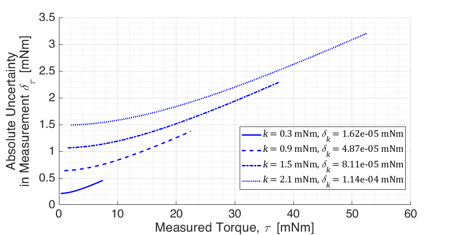
Figure 4: For four calculated torsional spring
constants, the absolute uncertainties were propagated for the full range of measurable
torques from 1° to 25°.
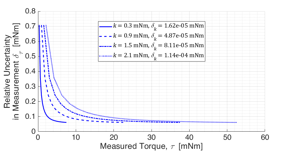
Figure 5: For the same calculated spring
constant values, the relative uncertainties were propagated from 1° to 25°.