4213
MRI Gradient Induced Device Heating of Active Implantable Medical Devices vs Gradient Magnetic Field (dB/dt rms)
Michael Childers1 and Shiloh Sison2
1Abbott, Sylmar, CA, United States, 2Abbott, Sunnyvale, CA, United States
1Abbott, Sylmar, CA, United States, 2Abbott, Sunnyvale, CA, United States
Synopsis
As part of the MR safety assessment for AIMDs per ISO/TS 10974, an evaluation for gradient induced device heating must be performed. For this evaluation, the temperature response of the device is assumed to be proportional to the square of dB/dt rms. While this has been shown to be true for simple structures like a conductive disk, no testing has been presented showing that this relationship is still valid for more complex AIMDs structures. In this abstract we therefore provide testing, on a representative AIMD, confirming gradient induced device heating for AIMDs is proportional to the square of dB/dt rms.
Introduction
For the assessment of MR conditional safety of Active Implantable Medical Devices (AIMD) there are many hazards to consider. One hazard, identified in ISO/TS 10974, is gradient induced device heating. The imaging gradient dB/dt field can induce eddy currents on conductive surfaces of an AIMD resulting in device heating.To test for gradient field induced device heating per ISO/TS 10974, the temperature response of the device is assumed to be proportional to the square of dB/dt rms1. While this has been shown to be true for simple structures like a conductive disk, no testing has been presented which shows that this relationship is still valid when applied to more complex structures like AIMDs containing a large variety of materials and shapes.
In this abstract we therefore look to evaluate the relationship between MRI gradient induced device heating and the time varying gradient magnetic field (dB/dt rms) for a representative AIMD.
Methods
MR gradient induced device heating testing was performed on an implantable cardiac defibrillator (ICD). An ICD is a representative AIMD as it contains a battery and internal circuity housed within a hermetically sealed enclosure. Gradient induced device heating testing was performed using the methods specified in the gradient heating clause of ISO/TS 10974 as described below.Fiber optic temperature probes were placed on the device surface at locations known to produce the highest heating (i.e. the device hotspot) along with 1 ambient probe placed near the edge of the test phantom to monitor background temperature changes. The approximate temperature probe placements on the device under test are shown in Figure 1. These temperature probes were used to monitor and record the devices temperature response throughout the test exposures with temperature measurements being recorded at least once every second.
For testing, the device was placed in a phantom filled with HEC gel with its major conductive surfaces orthogonal to the gradient field in order to maximize the effect of gradient heating. Using a research gradient magnetic field generator, the device was exposed to a pulsed gradient magnetic field using a sine waveform with a frequency of 1750Hz for a total of 15 minutes per exposure.
The device was tested five times for the gradient magnetic field dB/dt rms field strengths shown in Table 1. Between each run the device and surrounding gel was allowed to cool back down to room temperature before the next test run.
For each gradient field dB/dt rms exposure, the temperature rise of the device over the 15-minute exposure was calculated. The temperature rises were then plotted, and a regression analysis was performed.
Finally, the temperature rise data collected was scaled to the maximum dB/dt rms level of 50 T/s rms to determine the error between the measured and scaled temperature rises. Temperature rise scaling was performed using the following equation per ISO/TS 10974:
$$\triangle T_{scaled}=\triangle T_{measured}\left[ \frac{\frac{dB}{dt}_{rms}(scaled)}{\frac{dB}{dt}_{rms}(measured)}\right]^{2}$$
Results
The device under test was exposed to five separate gradient magnetic field exposures for the dB/dt rms values specified in Table 1. The measured temperature rise data (normalized for a scale between 0 and 1) for each probe/device location is shown in Table 2 and plotted in Figure 2. A 2nd order polynomial fit (with the linear coefficient and free term set to zero) was applied to the plotted test data which resulted in an R2 value greater than 0.999.The temperature rise data collected was then scaled to the maximum dB/dt rms level of 50 T/s rms per ISO/TS 10974. As can be seen in Table 3, the error between the scaled and measured temperature rise at 50 T/s rms was less than 5% for all measurements.
Note: Scaling for the lowest field strength (i.e. 10 T/s rms) was not included as the temperature rise did not meet the signal to noise ratio requirements per ISO 10974 for scaling.
Discussion/Conclusions
As can be seen in Figure 2, the temperature rise of the device with respect to dB/dt rms closely follows a 2nd order polynomial fit. This testing thus confirms that gradient induced device heating for typical AIMDs is proportional to the square of dB/dt rms.Acknowledgements
No acknowledgement found.References
1. ISO/TS 10974, 2018, "Assessment of the safety of magnetic resonance imaging for patients with an active implantable medical device" ISO, Geneva, Switzerland, www.astm.org.Figures
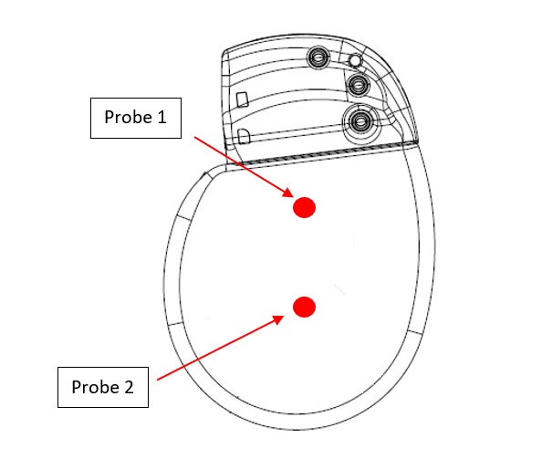
Figure 1 - Temperature Probe Locations
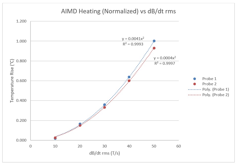
Figure 2 - Temperature Rise of AIMD device vs dB/dt rms
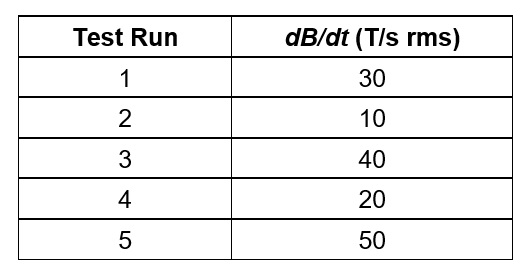
Table 1 - Gradient Test Field Strength per Run
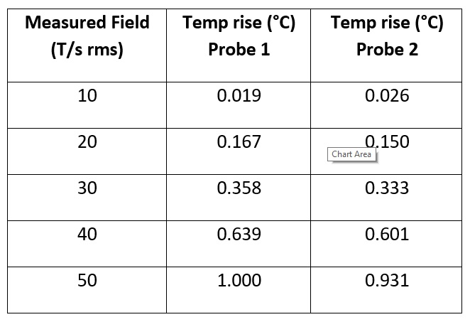
Table 2 - Normalized Temperature Rise of AIMD device
vs dB/dt rms
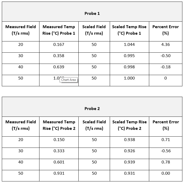
Table 3 - Scaled vs Measured Temperature Rise for 50 T/s rms