4212
Heating and torque of passive metallic implants by gradient dBdt and static field B0 in MRI1Electrical Engineering, Purdue University, West Lafayette, IN, United States
Synopsis
The objective was to calculate heating and torque, which results in vibration, by the time-varying magnetic field dBdt from the gradients in MRI to identify which passive implants will have the largest gradient interactions. A large hip stem and an acetabular hip shell were selected as worse case practical implants for gradient interactions. Maximum temperature rise under the intense dBdt inputs (42 T/s, 1750 Hz, 15 minutes exposure) of ISO/IEC 10974 is 5.4 $$$^{\circ}$$$C for the hip stem and 7.0 $$$^{\circ}$$$C for the acetabular shell. Gradient torque was about 4 times the gravity value for the acetabular shell.
Introduction
Gradient heating and vibration are presented in ISO/IEC 10974$$$^1$$$ as investigations that are required for an evaluation of MRI safety of active implants. Recently, FDA$$$^2$$$ and ASTM$$$^3$$$ have issued draft documents that request a review of gradient interactions for medical devices, including passive implants.The objective of this work was to calculate heating and torque, which induces vibration, due to the time-varying magnetic field dBdt from the gradients in MRI for passive implants in order to identify (1) what types of passive implants will have minimal gradient interactions and thus are candidates for being exempted from assessment of gradient heating and vibration and (2) which types of passive implants may exhibit sufficient gradient interactions to be candidates for further investigation.
In ISO/IEC 10974, equations are presented for gradient power deposition and gradient torque for conducting disks at low frequency. The time average power deposition is expressed as
$$P_{ave-disk} \ = \frac{ \sigma T\pi(dBdt-rms)^2R^4}{8} \;\; \; \;\; (1)$$
where $$$\sigma$$$ is the disk conductivity, T is the thickness, and R is the radius. The instantaneous torque is expressed as
$$ \tau_{disk} = \frac {1} {8} \sigma T \pi R^4B_0(dBdt) \; \; \;\;\; (2)$$
where $$$B_0$$$ is the static field.
Gradient interactions will thus be most significant for passive implants with large area, large electrical conductivity, and large metal mass.
Methods
Calculations were made with a custom FDTD program. Incident dBdt was a plane wave. The gradient induced heating and torque were calculated for dBdt rms = 42 T/s, frequency f of 1750 Hz, and 15 minute duration. There are the conditions currently set for the International Standard version of 10974. To speed the calculation, frequency was set to 3 MHz and conductivity of the metal was set to a factor $$$3 x 10^6/1750$$$ less than the true value, which is valid as eddy current distribution is a function of $$$ \sigma f $$$. The implants were immersed in non-convecting saline. The computational methods were validated by (1) comparing calculated and measured temperature rises for circular disks; and (2) by confirming low frequency power and torque agreed with equations (1) and (2).Gradient torque is due to the interaction of the eddy currents induced in implant by dBdt with the static field of the MR magnet. Gradient torque tends to be greatest with the static field parallel to the plane of the implant and with dB/dt perpendicular to the plane of the implant. The torque was calculated as
$$ \tau_{gradient} = \int_{implant} \mathbf { r \times (J \times B) } \; dV \;\;\;(3)$$
where $$$ \mathbf r $$$ is a position vector, $$$ \mathbf J $$$ is the current density in the implant, $$$ \mathbf B $$$ is the external magnetic field and dV is a volume element.
In response to the torque, the unconstrained implant will vibrate about its center of mass. In the patient, tissue restraining forces will limit the vibration amplitude.
Results
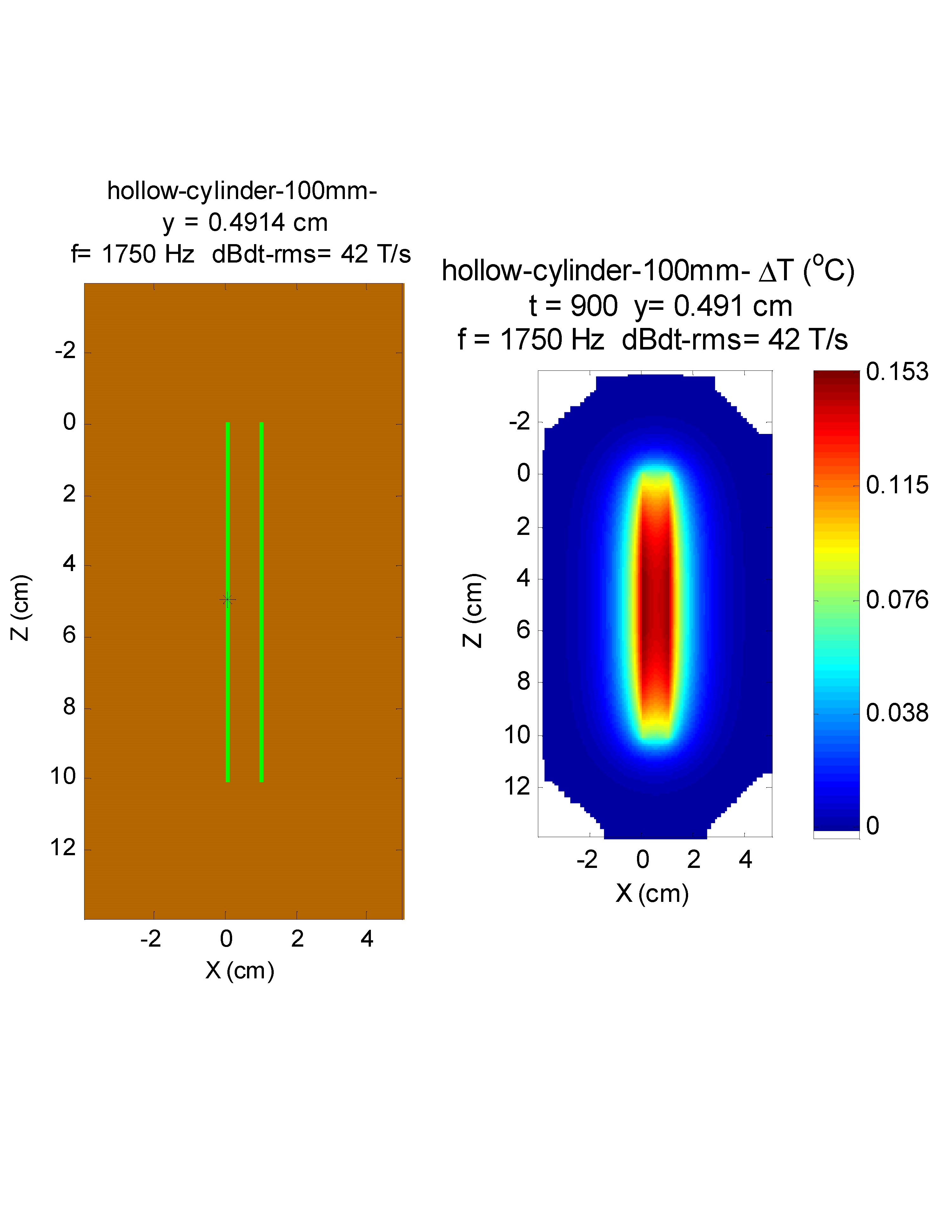
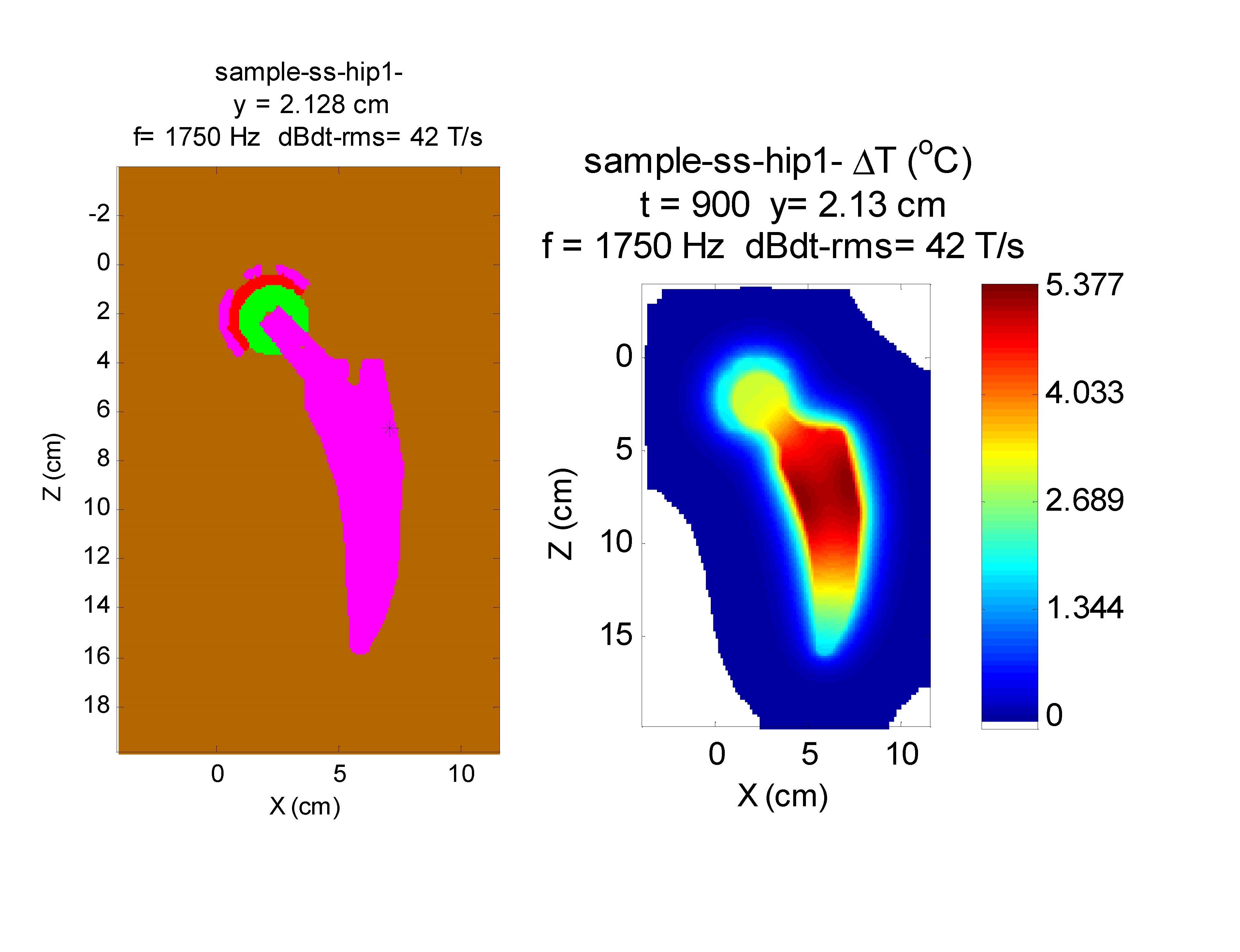
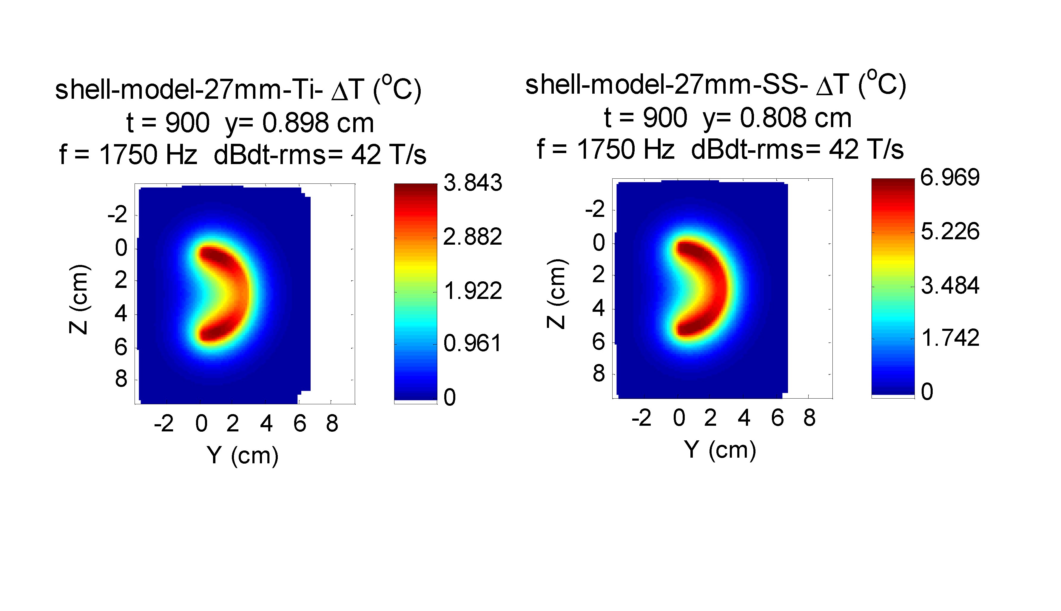
Figure 1 shows a cylindrical shell that represents a beyond worse-case model for a stent. The maximum temperature rise is less than 0.2 $$$^{\circ}C$$$.Figures 2 and 3 represent worse case practical implants for gradient interactions. Figure 2 shows a a hip stem and Figure 3 shows an acetabular shell. Greatest interaction is for stainless steel 316, which at $$$1.35 \times 10^6 $$$ S/m has the greatest electrical conductivity of metals commonly used in orthopedic implants. Maximum temperature rise under the intense dBdt inputs of ISO/IEC 10974 is 5.4 $$$^{\circ}$$$C for the hip stem and 7.0 $$$^{\circ}$$$C for the acetabular shell. Maximum torque for these two implants is 0.28 N-m for the acetabular shell, which is a factor of about 4 greater than the gravity torque of 0.068 N-m.
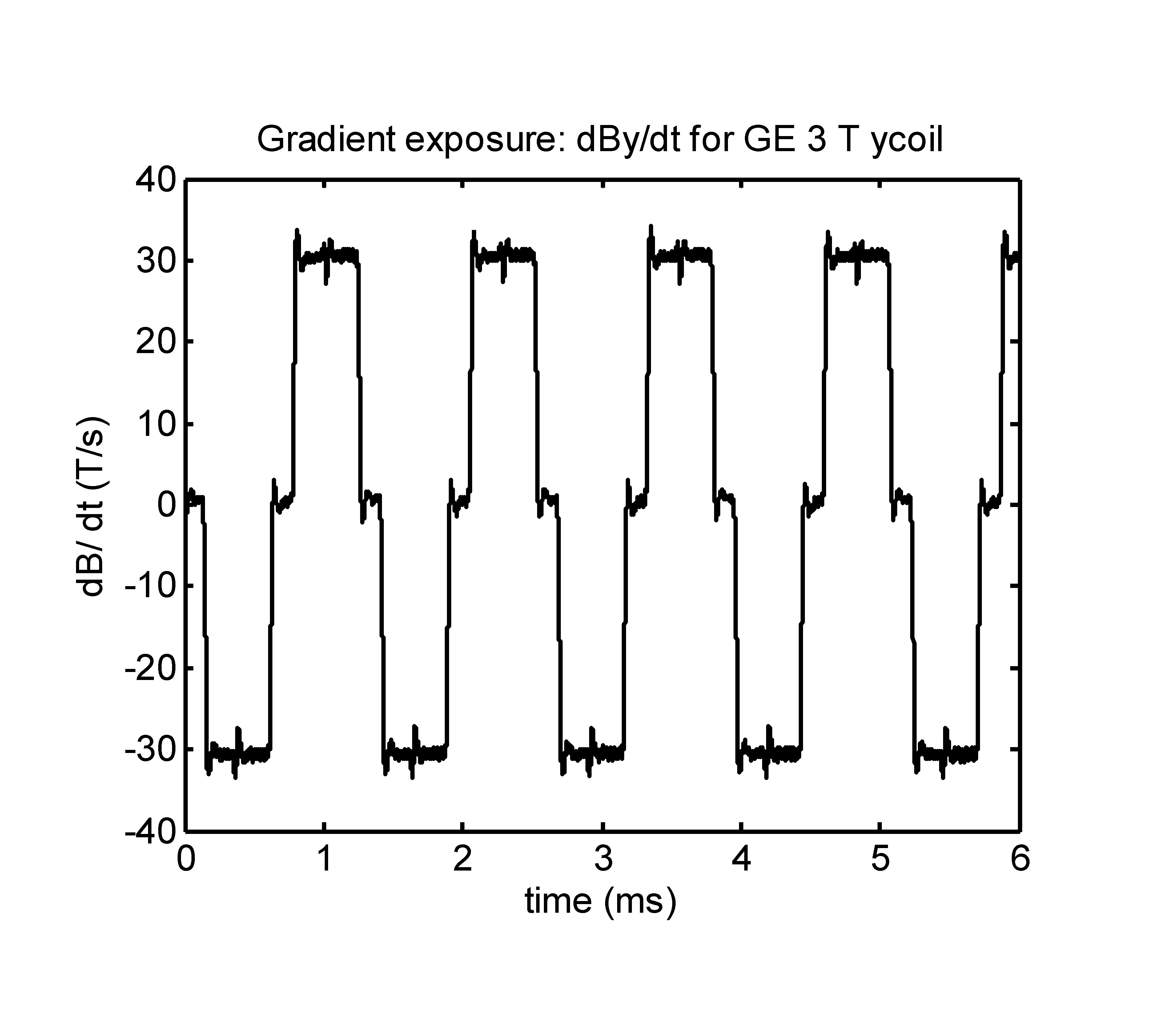
Figure 4 shows a measured dBdt waveform from an EPI sequence in a GE 3T MR system.This waveform produced intense vibration in a sample silver disk of 89.5 mm diameter and 3.77 mm thick. The torque under this condition was calculated to be about 5 N-m, a factor of about 20 greater than for the acetabular shell.
Figure 5 plots the gradient power relative to the low frequency value of Eq. 1 for circular disks. For alloys used in passive implants, gradient power at 1750 Hz is not too different from the low frequency values. More conductive materials, which may be used in active implants, have significant reduction in gradient power at higher frequency.
Discussion and Conclusions
For gradient inducted heating or vibration of the metal of an implant to be of clinical significance, all of the following conditions need to be present.1) Metallic implant with large and symmetric surface area and thick metal.
2) dBdt normally incident on the large surface of implant.
3) Large sustained gradient slew rate.
4) Implant is located in region of the bore where dB/dt is most intense.
Among frequently used passive implants, an acetabular hip shell exhibits the greatest gradient interaction. However even for this device, an adverse impact on the patient is only possible if there are multiple worse case scenarios simultaneously occurring. Gradient interactions for stents and similar implants with significantly less mass and area than the acetabular shell will be minimal.
Acknowledgements
The gradient waveform in Figure 4 was recorded in the GE Discovery 750 3T MR system at the Purdue University MRI center. L. Young operated the MR system.References
1. International Organization for Standardization, ISO/TS 10974:2018, Second Edition. Assessment of the safety of magnetic resonance imaging for patients with an active implantable medical device, 2018.
2. US Food and Drug Administration (FDA), Testing and Labeling Medical Devices for Safety in the Magnetic Resonance (MR) Environment. Draft Guidance for Industry and Food and Drug Administration Staff, August 2, 2019.
3. ASTM International, F2503, Standard Practice for Marking Medical Devices and Other Items for Safety in the Magnetic Resonance Environment, draft version, October 2019.
4. Brühl
R, Ihlenfeld A,. and Ittermann B, Gradient Heating of Bulk Metallic Implants
Can Be a Safety Concern in MRI: Mag. Reson. Med. 2017:77:1739-1740.
Figures