4210
Quench Dynamics Across Multiple Field Strengths1The xMR Labs, Physics and Astronomy, Western University, London, ON, Canada
Synopsis
Modern MR developments have allowed for systems which can easily vary the main magnetic field to leverage tissue properties at different field strengths. With this comes a change in the way that these systems handle safe elimination (quench) of main magnetic field in emergency situations. These quench dynamics at variable fields were investigated using a magnetic field probe at the isocenter in the bore of the magnet. The measured propagation dynamics show the need to ensure that the quench circuit used maintains an acceptable quench time, as quench times at the maximum field may not translate to lower field.
Introduction
Development of cryogen-free MR systems has allowed for the main field to be quickly and easily varied without helium boil-off, leading to unexplored applications. Additionally, with modifications, standard high field MR systems can be run at lower field strengths to take advantage of reduced susceptibility artefacts while still maintaining state-of-the-art MR components1. To ensure system safety, methods for eliminating the main field (quenching) need to adapt to variable current in the magnet.Generally, a quench is initiated by heating the magnet above critical temperature where the wire becomes non-superconducting and allowing the system to then propagate the expansion of the non-superconducting region while protecting from damaging the rest of the MR components. The critical temperature of each coil in the magnet is affected by the field the system is set at due to a change in current. Passive quench protection circuits must be designed to operate at the lowest current the magnet is expected to be run at, as it is a priority to ensure the magnet itself is not damaged by the heating which occurs in the magnet coils during this process2.
In this paper, we delve into quench propagation behaviours of a prototype cryogen-free magnet and show results from a preliminary study on the change in the static field during an emergency quench at a variety of fields and model the behaviour of these quenches.
Methods
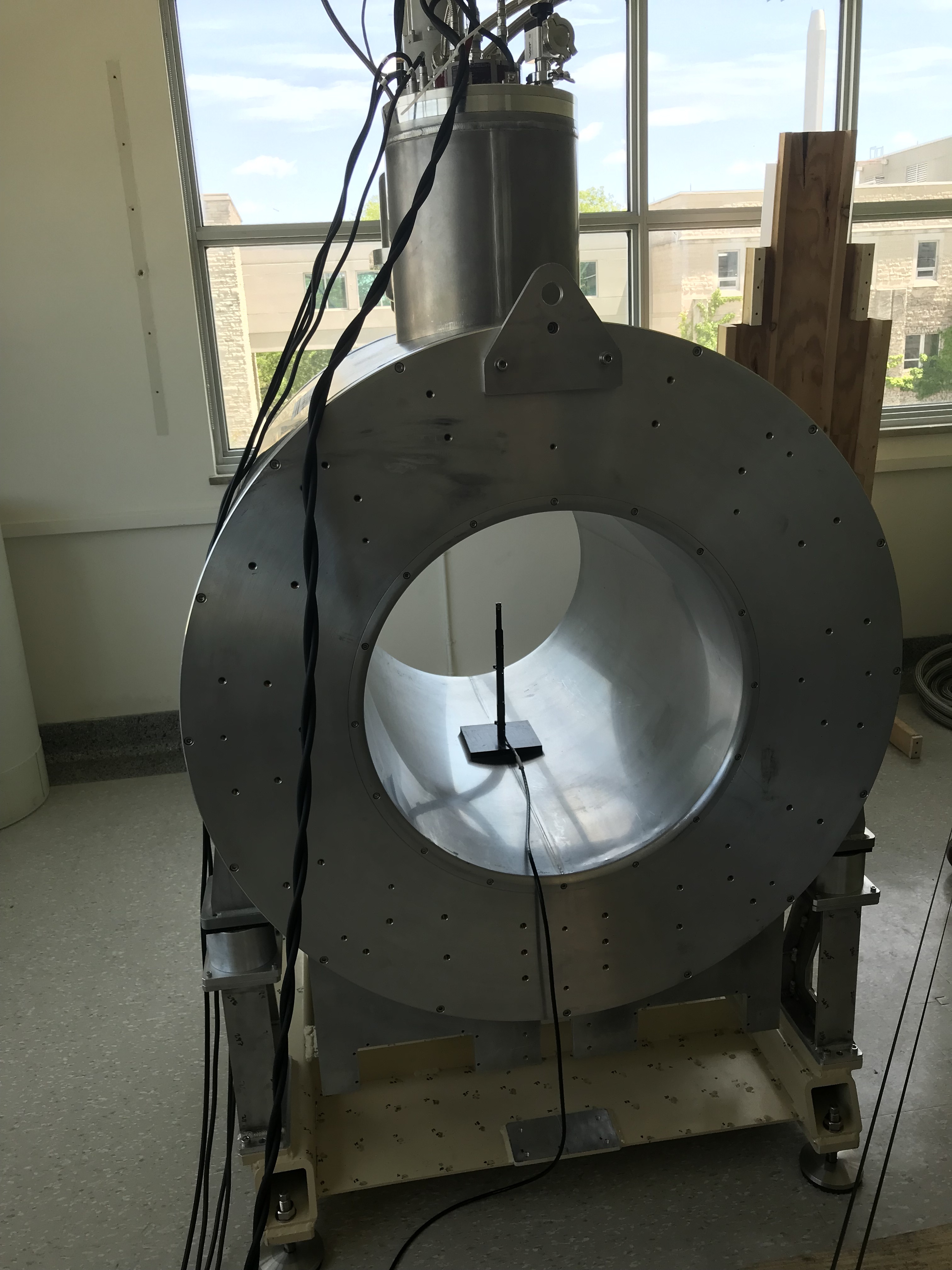
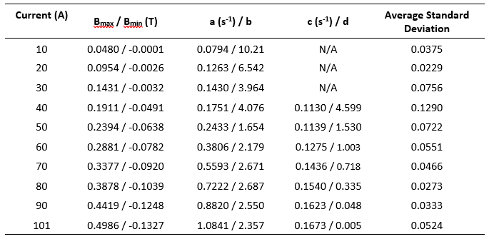
The quench dynamics were investigated using a calibrated magnetic field probe placed at the isocenter inside the bore of a cryogen-free superconducting magnet (Figure 1) designed to operate at a maximum field of 0.5T at 101A. The field probe voltage output and the voltage of the quench circuit were recorded with an NI DAQ system, using a LabVIEW program, with data collection occurring until recorded field had settled to less than 5 Gauss. Ten quenches were conducted with current varying between 10A and 101A (maximum current). The analysis of the quench was done using MATLAB and Python to optimize a fit using a plateaued difference of exponentials to model the behaviours of the main field coils and the shielding coils. The model of the quench was then used to test the predicted settling time (time elapsed until the field measured reached 5 Gauss).Results
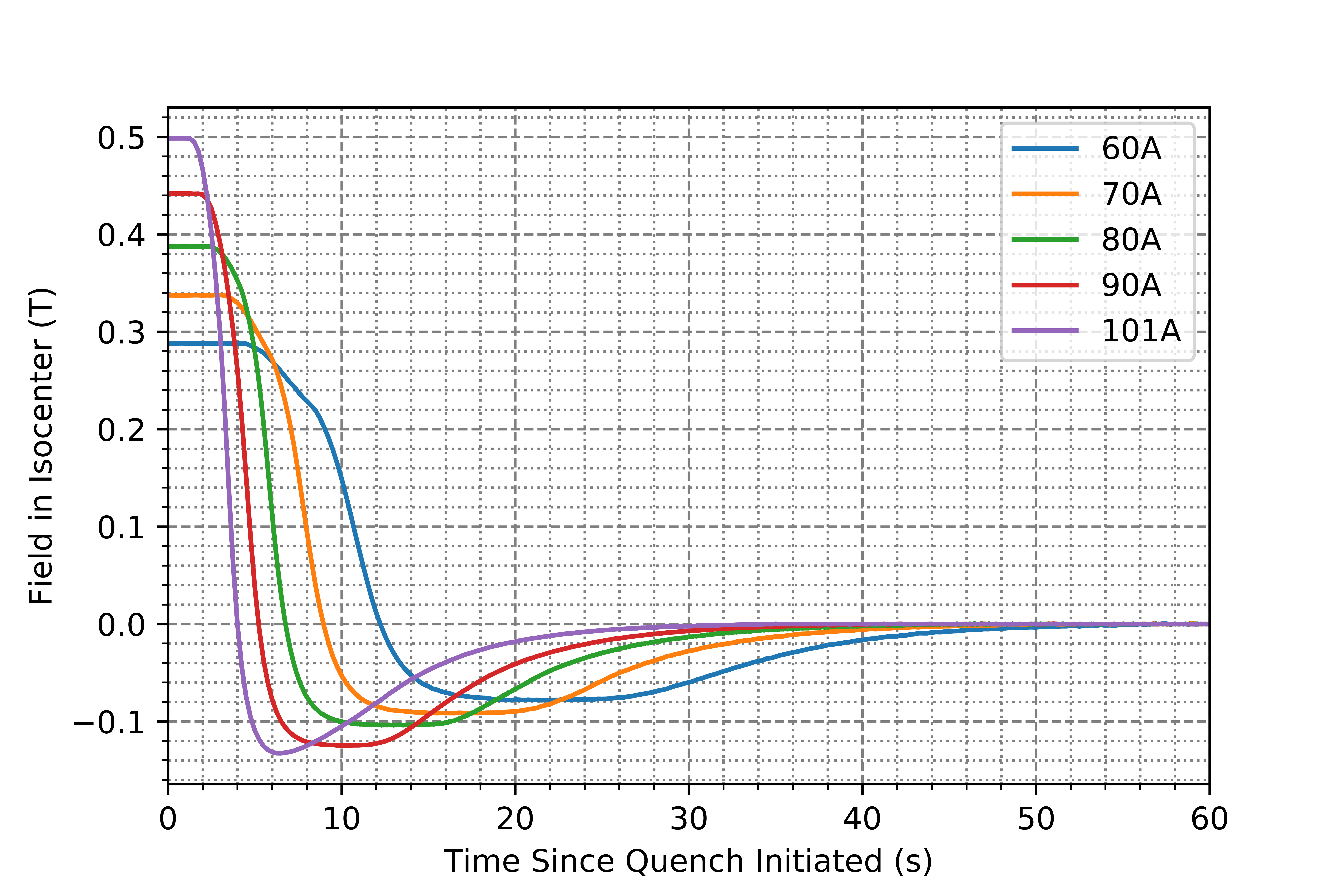
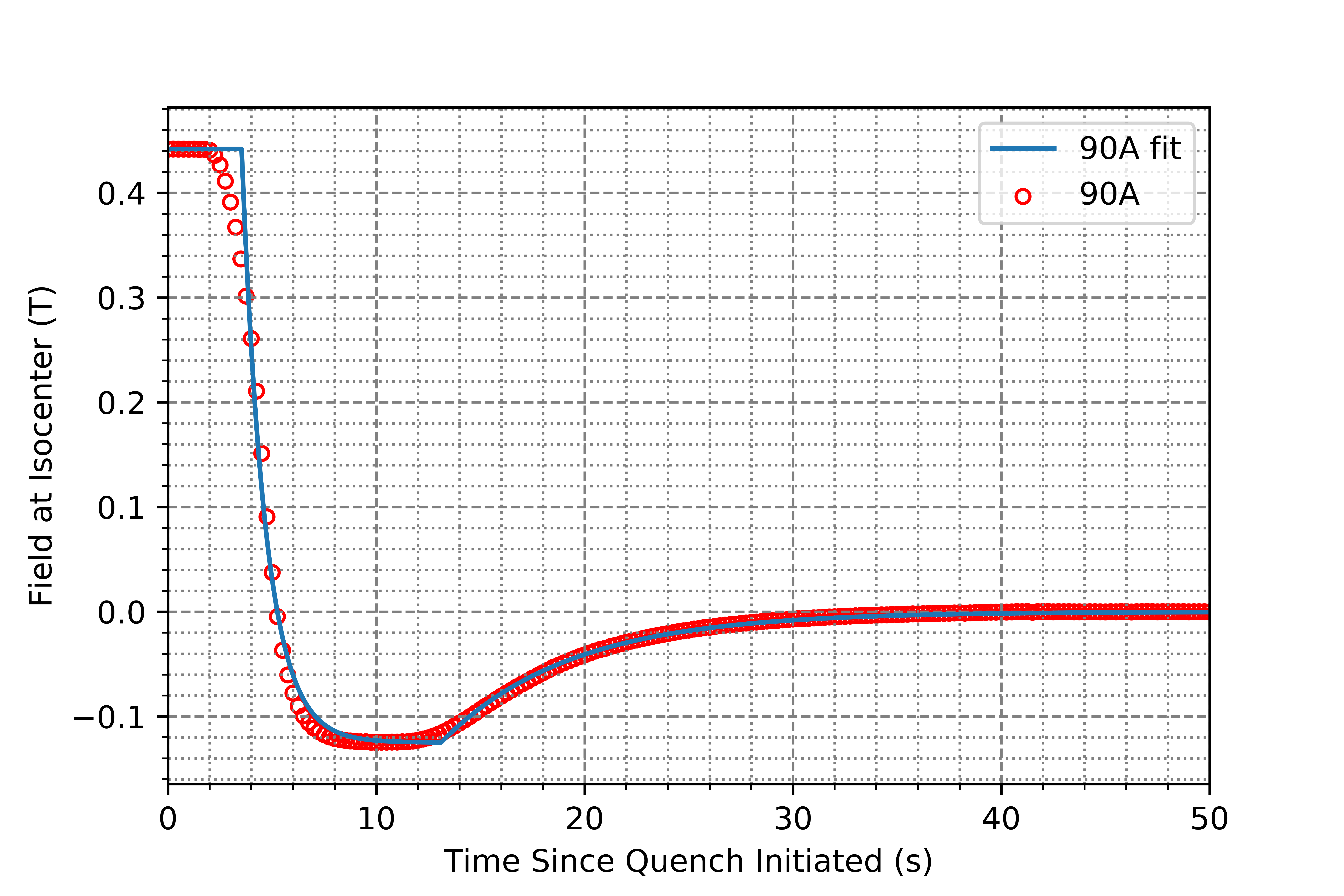
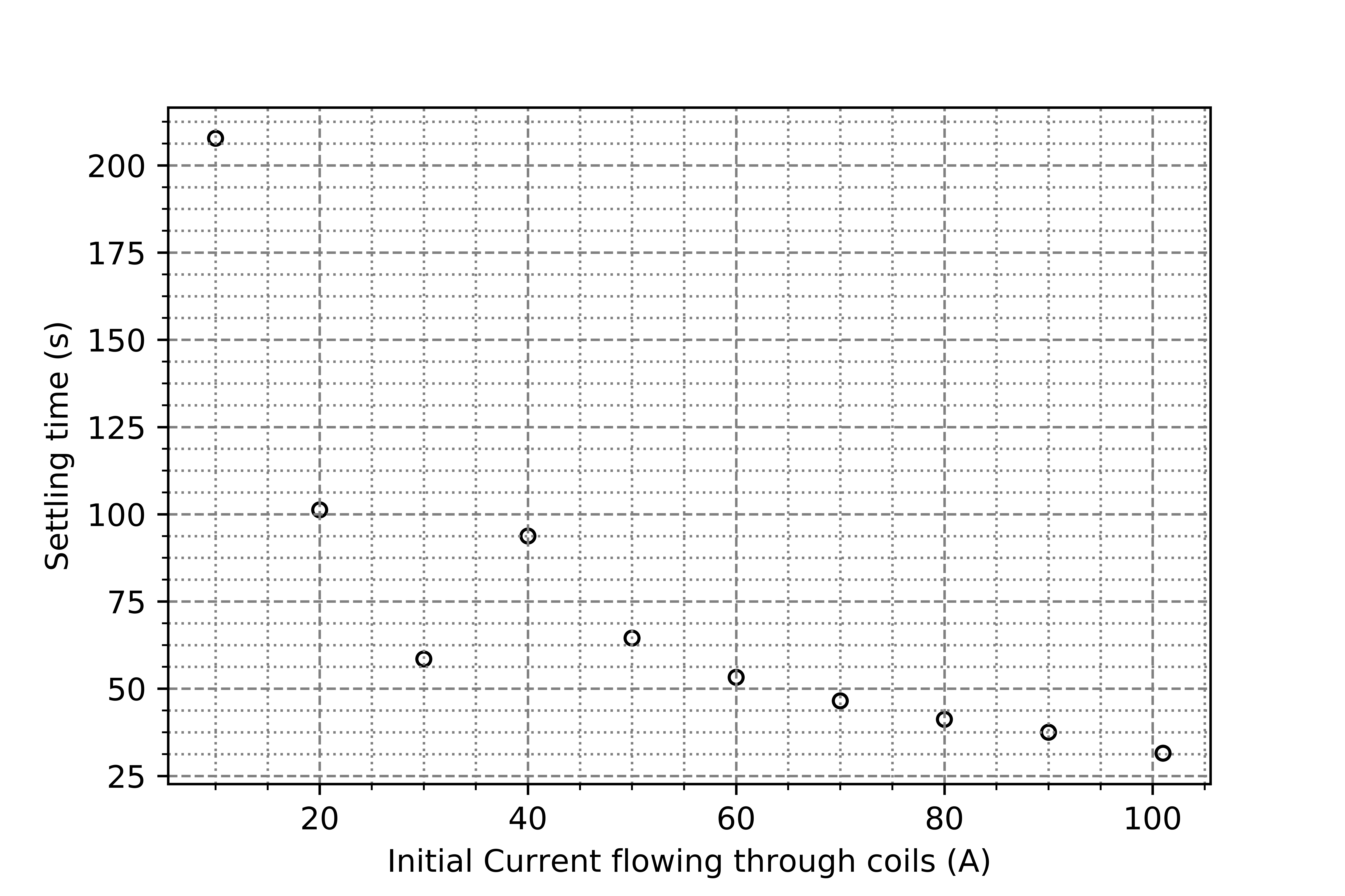
Figure 1 shows a photograph of the main magnet with the field probe in the isocenter of the magnet. The field dynamics for a set of quenches from 60A to 101A is shown in Figure 2, and a sample quench evolution alongside a difference of exponentials fit is shown in Figure 3. The complete set of parameters used to model the quenches is reported in Table 1, along with the mean standard deviation error of the parameters optimized. In Figure 4, the settling time to the 5 Gauss level is shown as a function of the initial current through the coils.Discussion
As expected, the difference of exponentials fit is a suitable model of the dynamics of the quench behaviour observed. Lower standard deviation suggests that the fit is effective at the ends of the current range and it is hypothesized that the delays in propagation of the quench results in a less serviceable fit in some of the trials. Importantly, the fits show that the time taken to quench the system increases as the starting field is reduced. This behaviour is proposed to be due to the increase in critical temperature as the field falls at the location of the superconductor. The magnetic field flips from the initial orientation is likely due to the shield coils being the last to quench. Below 40A, the quench occurs as a single step, simply settling to zero and not reversing field direction. The two regimes of behaviour can be seen with the entire system quenching in one step at lower current, and at higher currents the shield coils being the last coils to quench causing the settling time to take longer at 40A and 50A than at 30A.In order to improve the settling time in this magnet, the quench circuit could be amended to deposit more heat (so that the delay in quench beginning is reduced) and the heating elements on the shields and primary coils could be better balanced to make the quench simultaneous.
Conclusion
In this work, we have conducted a preliminary study looking at the quench behaviour and settling times for a variable field cryogen-free superconducting magnet which has shown the varying propagation dynamics as the current flowing through the magnet changes. In broader applications, this work shows the need to consider the changes in how an MR system handles a quench at different field strengths. Simply because a quench occurs in an acceptable time at the maximum field strength, does not mean that the quench time will remain constant or decrease as the current through the coils is reduced. Depending on the current flowing through the magnet, increasing the number of quench heaters to reach critical temperature more quickly or changing to a less conservative quench protection circuit based on the current to allow the quench to propagate faster.Acknowledgements
The authors would like to acknowledge support form NSERC and the Ontario Research Fund.References
1. Campbell-Washburn A. E., Ramasawmy R., Restivo M. C., et al. Opportunities in interventional and diagnostic imaging by using high-performance low-field-strength MRI. Radiology, 2019;293(2), 384-393.
2. Seeber B (Ed.). Handbook of applied superconductivity (Vol. 2). CRC press; 1998.
Figures