4208
Thermal effects produced by gradient switching of Echo-Planar Imaging sequences in metallic hip implants
Alessandro Arduino1, Oriano Bottauscio1, Mario Chiampi1, and Luca Zilberti1
1INRiM, Torino, Italy
1INRiM, Torino, Italy
Synopsis
The temperature increase induced by MRI gradient fields switched according to EPI sequences in a metallic hip implant is evaluated with an accurate numerical model. The role of the body position within the scanner, of the frequency encoding direction and of the thermoregulation is studied and discussed. The results show that the eddy currents generated by the gradient coils in the implant are sufficient to induce a temperature increase of some kelvin (without accounting for the RF power deposition); moreover, it results that the biological effect can be controlled by choosing properly the frequency encoding direction.
Introduction
The increasing number of patients with metallic orthopaedic implants imposes safety issues associated with their MRI examination, because of the strong interaction between the time-varying electromagnetic fields (EMF) and the high conductivity components.While the direct heating of tissues correlated with the exposure to radiofrequency fields is largely analysed in literature, less attention is devoted to the thermal effects due to the switching Gradient Coil (GC) fields. However, experimental1,2, theoretical3 and computational4,5 results show possible significant temperature increase in the tissues due to the diffusion of the heat produced inside the implant by eddy currents.
Here we use a computational code, specifically developed, to evaluate the heating generated in a patient with a unilateral hip prosthesis when undergoing an Echo-Planar Imaging (EPI) sequence and analyse the influence of some parameters (body position, frequency encoding direction, thermoregulation) on the thermal stress. The results reported in this digest represent a selection of data recently published by the Authors7.
Method
The limited temperature increase (few kelvin) allows us to handle separately the electromagnetic and the thermal problems. The electromagnetic problem is solved only inside the implant, discretized into voxels, assuming that the currents induced into the body tissues neither modify the GC magnetic field, nor generate significant thermal power. The signals of the GC switching sequence are divided into sub-signals. Each sub-signal is expanded in a truncated Fourier series and the related EMF solutions are computed in the frequency domain through a hybrid Finite Element/Boundary Element method. The electric fields in each implant voxel are moved in time domain and superimposed, sub-signal by sub-signal and coil by coil, to reconstruct the instantaneous evolution of the electric field and the Joule power density. The strategy of signal subdivision significantly reduces the computational burden (a reduction around 90 % is estimated for the EPI sequence).The thermal problem is modelled through Pennes’ equation inside the human body using the Joule power densities previously computed as forcing terms. The voxelized human model allows the application of the finite difference method with the Douglas–Gunn time split implemented on GPUs.6 The whole computational procedure has been validated by comparison with experiments on an acetabular cup inside a phantom2,7.
Results
A unilateral right implant with acetabular shell and liner is inserted in the “Duke” anatomical model of the Virtual Population, involving 77 tissues, whose electric and thermal properties are included in the IT’IS Foundation database. The metallic components are made of CoCrMo alloy, Ti6Al4V alloy or austenitic stainless steel. The human model is placed inside a tubular MRI scanner, whose GC generates the magnetic flux density spatial distributions of Fig. 1. The EPI sequence, shown in Fig. 2, is executed continuously for about 12 minutes.The computations are performed moving the body along the scanner axis, varying the coordinate zf of the femoral head with respect to the MR isocenter in the range from -450 mm to +300 mm. The x and y coordinates of the implant are maintained in the “natural” position. The results, summarized in Fig. 3 in terms of temperature increase with respect to the local temperature before the exposure, show that, for the CoCrMo alloy implant, the maximum and minimum heating are reached for |zf|=300 mm and zf=0, respectively.
The change of the imaging plane, and the consequent role of the three GCs, affects the thermal stress sensibly. Figure 4 compares the maximum temperature elevation reached for all possible configurations and implant materials with the femoral head at zf=-300 mm. The values indicate that the six configurations could be grouped in three couples having the same frequency encoding direction and the same maximum temperature increase. These results highlight the essential role of the direction of the frequency encoding whose signals produce most of the power losses. Moreover, it can be appreciated how the temperature increase is proportional to the electric conductivity of the implant.
The effect of the thermoregulation is found to be very low (the variation of the maximum temperature is always less than 0.15 K), even assuming an instantaneous biological reaction.
Discussion
The effects of GCs are usually stronger when the implant is placed in the scanner periphery, where the Bz component is higher and significant concomitant components Bx (or By) are generated by X and Y GCs.For the EPI sequence, the frequency encoding direction determines the amount of the heating. Hence, if the Y GC plays this role, the temperature elevation significantly reduces, because of the relatively low field produced by such a coil throughout the volume taken up by the hip implant.
The thermoregulation affects the results only slightly, due to both the limited temperature increase and the relatively low basal blood perfusion coefficient of the tissues surrounding the prosthesis.
Conclusion
The computed results put in evidence that the GC heating effects must be taken into account for a reliable evaluation of the safety conditions in a patient with metallic hip prosthesis when undergoing MRI. The same investigations also suggest safety measures which could reduce the thermal stress (e.g., change of the imaging plane, use of 'less aggressive' sequences or introduction of waiting times).Acknowledgements
The results here presented have been developed in the framework of the 17IND01 MIMAS Project. This project has received funding from the EMPIR Programme, co-financed by the Participating States and from the European Union’s Horizon 2020 Research and Innovation Programme.References
- Graf H, Steidle G, Schick F Heating of Metallic Implants and Instruments Induced by Gradient Switching in a 1.5-Tesla Whole-Body Unit. J Magn Reson Im. 2007;26:1328–1333.
- Bruehl R, Ihlenfeld A, Ittermann B. Gradient heating of bulk metallic implants can be a safety concern in MRI. Magn. Reson. Med. 2017; 77:1739-1740.
- Zilberti L, Arduino A, Bottauscio O, et al. The Underestimated Role of Gradient Coils in MRI Safety. Magn Reson Med. 2017, 77:13-15.
- El Bannan K, Handler W, Chronik B, et al. Heating of Metallic Rods Induced by Time-Varying Gradient Fields in MRI. J Magn Reson Im. 2013, 38:411-416.
- Zilberti L, Bottauscio O, Chiampi M, et al. Numerical Prediction of Temperature Elevation Induced around Metallic Hip Prostheses by Traditional, Split, and Uniplanar Gradient Coils. Magn Reson in Med. 2015; 74:272–279.
- Arduino A, Bottauscio O, Chiampi M, et al. Douglas-Gunn Method Applied to Dosimetric Assessment in Magnetic Resonance Imaging. IEEE Trans Magn 2017; 53:5000204.
- Arduino A, Bottauscio O, Bruehl R, et al. In silico evaluation of the thermal stress induced by MRI switched gradient fields in patients with metallic hip implant. Phys Med Biol, in press. DOI: 10.1088/1361-6560/AB5428.
Figures
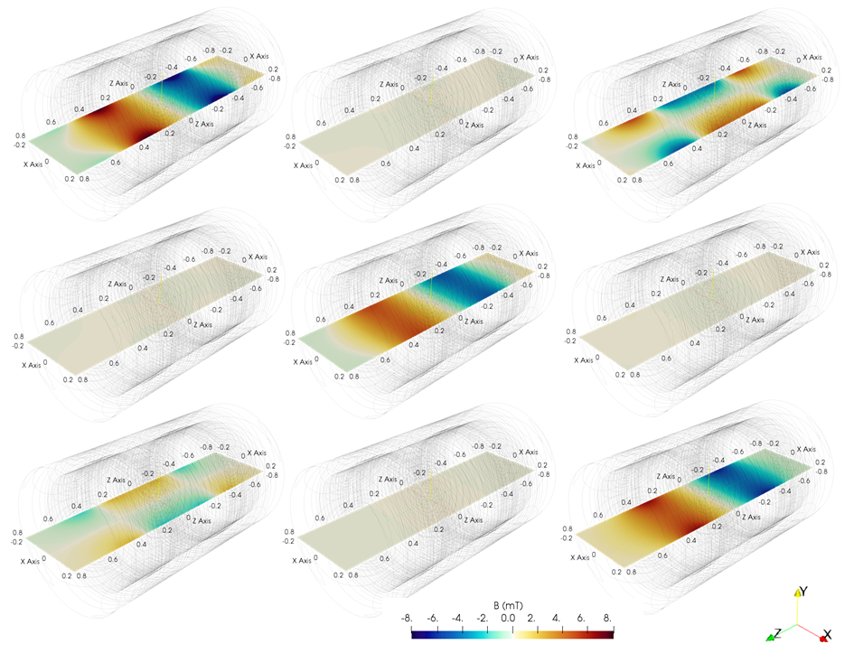
Spatial
distribution of the GC magnetic flux density components (mT) along the
mid-plane (plane x-z) of a tubular scanner for a rated gradient of 20 mT/m.
From left to right, the components Bx, By and Bz generated by GC for gradient X,
Y and Z (from upper to lower, respectively).
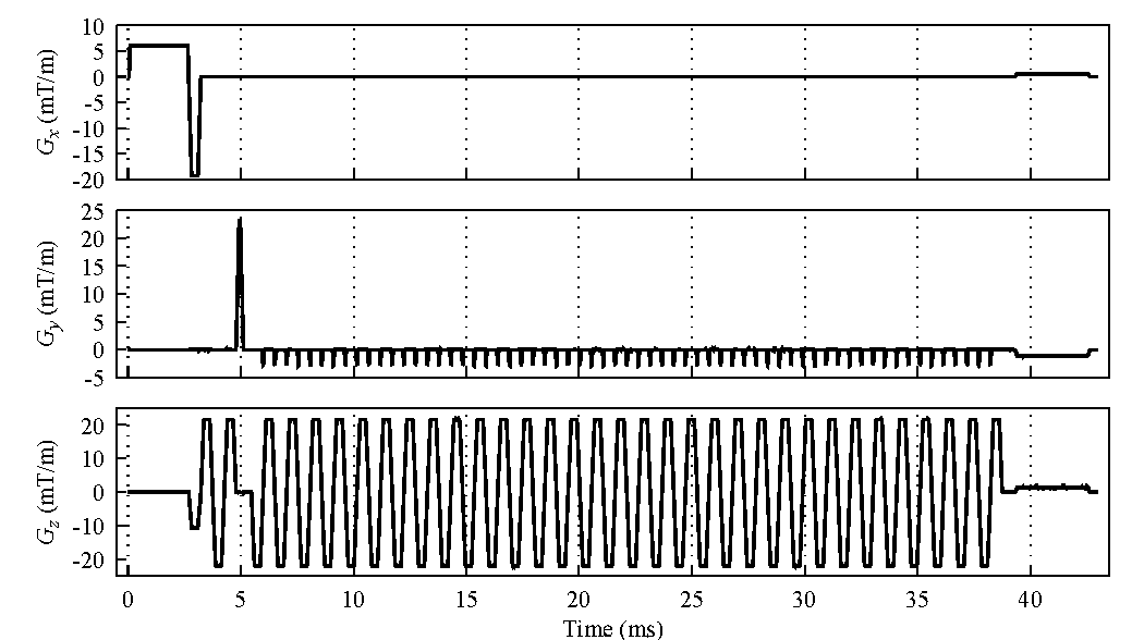
Gradient evolution for the EPI sequence (time
frame = 43 ms) for a sagittal scan (Gx: Slice Selection, Gy: Phase Encoding,
Gz: Frequency Encoding). The signal have been recorded from nominal-current
monitor of the gradient amplifier of a Siemens Verio 3 T scanner.
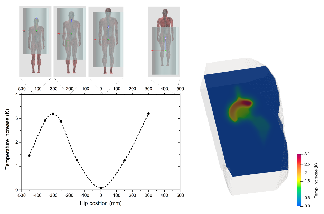
Maximum temperature increase in the implant
(after 12 minutes of exposure) versus the coordinate zf of the femoral
head of the hip implant made of CoCrMo alloy. The body position with respect to
the MRI isocenter is also depicted. On the right, spatial
distribution of the temperature increase for the position of maximum heating.
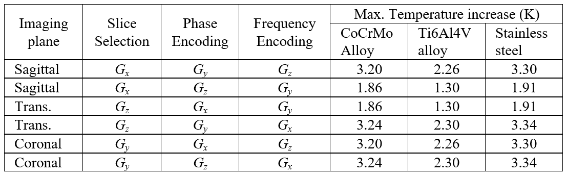
Maximum temperature increase (after 12 minutes
exposure) for six possible configurations and three considered materials.