4205
Validating low frequency QS solvers in SEMCAD and Sim4life for simulating the effects of gradient fields on devices
Arjama Halder1,2, Ali Attaran2, William B Handler2, and Blaine A Chronik2
1Medical Biophysics, Western University, London, ON, Canada, 2Physics and Astronomy, Western University, London, ON, Canada
1Medical Biophysics, Western University, London, ON, Canada, 2Physics and Astronomy, Western University, London, ON, Canada
Synopsis
A validation study to ensure the EM behavior predicted by the quasi-static solvers in SEMCAD and Sim4Life is accurate.
INTRODUCTION
SEMCAD and Sim4Life are commercially used for device testing purposes, however, there are no validation studies performed that suggest the behavior predicted by these solvers are correct or consistent across different versions. The electromagnetic interaction between active implantable medical devices (AIMDs) and gradient coils, something that can be studied using these solvers, is a cause of concern as suggested in the ISO/TS 10974:20181,2, which makes it necessary to validate these solvers. Such a validation will ensure that the behavior predicted by the solvers are accurate, allowing device testing companies to correctly identify the class of devices that require physical testing, which will effectively reduce operating expense and test time.Here we perform a validation study for SEMCAD and Sim4Life, by simulating a conductive cylindrical phantom within a test coil that is built to produce homogeneous changing fields similar in size to those of gradients and operate in the kHz range. These simulations were validated with measurements of electric and magnetic fields within the coil.
METHOD
For the purpose of this abstract a cylindrical phantom made up of acrylic material with a thickness of 1.33 cm, inner diameter of 22.8 cm and length of 30.9 cm was filled with saline (conductivity of saline = 0.47 S/m) up to the height of 10 cm and placed within a test coil as shown in figure 1. The test coil used is a split solenoid (the split was designed for increased homogeneity) that create a switched-field (dB/dt) exposure system3.The benefit of such an external test platform is it avoids the operating expense and difficulties of testing in an MR scanner. The current applied to this exposure coil was sinusoidal in nature with a peak value of 80 A. Simulation studies were performed using low frequency magneto quasi-static solvers available in Sim4Life and SEMCAD. The vector potential generated within the dB/dt exposure coil was calculated using the Biot-Savart law in the quasi-static regime4. The solver used the curl of the vector potential to calculate the magnetic field and computed the electric field using tricubic interpolation. This electric field was perturbed due to the presence of a conducting phantom within the coil, as will be the case in the presence of any AIMD. All boundary conditions were neglected as zero Neumann boundary conditions, i.e., vanishing normal flux. The tolerance for convergence had a relative value of 10-8.This simulation study was validated with measurements performed using an ultra-low frequency electric field and a dB/dt probe. The electric field probe5 was constructed using a short dipole connected to a 2-stage instrumentation amplification phase that provide differential amplification followed by a difference amplifier stage that removes the common-mode voltage. The 3D dB/dt probe which led to the calculation of the magnetic field is composed of three sets of perpendicular loops around a common center. The calibration factor associated with the electric and dB/dt probe are 2.64 (V/m)/V and 50 (T/s)/V respectively. A robot equipped with 3 Nema 23 stepper motors and driven with a controller was used to accurately place the probes within the volume of the phantom. Data from the probes were collected using an oscilloscope as the recording device, with a termination impedance of 1 MΩ, to determine the peak electric field and dB/dt at each location inside the phantom. To remove extrinsic influences on voltage changes observed in the measurements, the saline solution was grounded.
RESULTS
The experimental setup along with the schematic is shown in figure 1. Figure 2 show the simulated electric and magnetic field on the xy plane at the center of the coil as predicted by Sim4Life and SEMCAD. Figure 3 compares the measured with the simulated results of the electric and magnetic fields along the line y = 0 on the xy plane at the center of the coil. Figure 4 shows the average percent difference error between a volume of measured and simulated data for both electric and magnetic field.DISCUSSION
Fig. 2a suggests a circulating electric field with peak values near the edges of the phantom and a drop off at the center as expected. Fig. 2b shows a largely homogeneous magnetic field along the test coil axis, with peak values within the phantom while a drop off is seen near the edges. Figure 3 suggests there is a strong agreement between the measurements performed and the simulated behavior for both electric and magnetic fields within the coil. The average percentage error for the electric and magnetic field experienced between simulation platforms and measurements is less than 10%. This allows us to conclude that these solvers can correctly map the electromagnetic environment within a gradient coil, thus providing a method to study the interactions between gradient coils and AIMDs.CONCLUSIONS
The electromagnetic interaction between gradient coils and AIMDs is an important consideration factor for device manufacturing companies as suggested by the ISO/TS 10974:2018. This abstract aims to provide a validation study which suggest that these low-frequency quasi-static solvers available in Sim4Life and SEMCAD allow us to accurately simulate these electromagnetic interactions.Acknowledgements
The authors would like to thank the research and financial supports received from Natural Sciences and Engineering Research Council (NSERC) of Canada, the Ontario Research Fund (ORF), and CMC Microsystems.References
- Gimbel JR, Kanal E. Can patients with implanted pacemakers safely undergo magnetic resonance imaging? J. Amer. College Cardiol.2004;43(7):1325–1327.
- International Organization for Standarization. Assessment of the safety of magnetic resonance imaging for patients with an active implantable medical device. ISO/TS 10974. 2018;4.
- Martire DJ, Handler WB, Chronik BA. Design of an MRI Gradient Field Exposure System for Medical Device Testing. ISMRM. 2017; Abstract # 4334.
- Roth BJ, Cohen LG, Hallett M. The Electric Field Induced During Magnetic Stimulation. Magn Mot Stimul Basic Princ Clin Exp. 1991;43:268-278.
- Halder Arjama, Attaran A, Handler WB, Chronik BA. Electric Field Probe used for Gradient Coil Induced Field Measurements During Medical Device Testing: Design, Calibration and Validation. IEEE Transactions on Antennas and Propagation. 2019; ID # AP1907-1282.R1. (Under review)
Figures
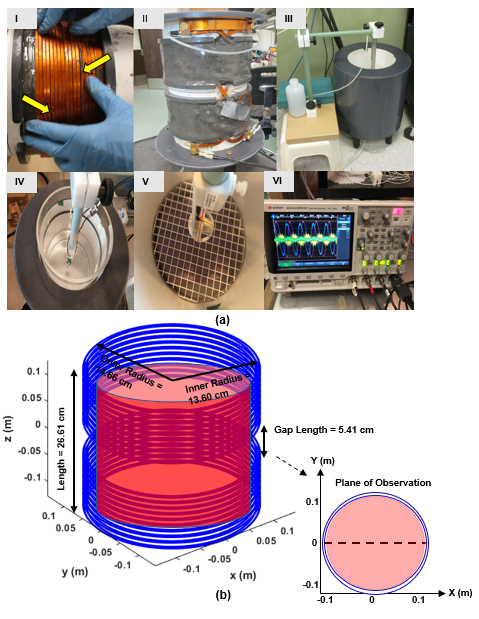
Fig. 1. (a) I: Close-up of the windings during construction. Voids can
be seen between windings due to wire-twisting (arrows). II: The side view of
the uncovered coil. III: Completed coil with positioning apparatus. IV: Shows
the saline filled cylindrical phantom within coil with the ultra-low frequency
electric field probe V: Shows the saline filled cylindrical phantom within coil
with the dB/dt probe. VI: Shows the signal trend on the oscilloscope. (b) The schematic for the
setup along with the information of the dB/dt exposure coil.

Fig. 2. (a) Simulated
electric field (b) Simulated magnetic field generated on the xy plane at the
center of the coil using Sim4Life and SEMCAD .
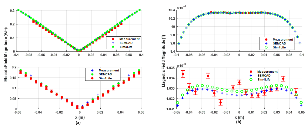
Fig. 3. (a) Shows the electric field measurements and the simulated results along the line y = 0 on the
xy plane at the center of the coil (b) Shows the magnetic field measurements and the simulated results along the line y = 0 on the xy plane at the center of the
coil.
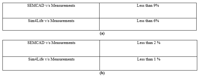
Fig. 3. (a) The
average percentage difference error between a volume of simulated and measured electric
field data. (b) The average percentage difference error between a volume of simulated and measured magnetic field data.