4201
Direct Comparison of In situ Cadaveric Pacemaker Lead-tip Heating to In vitro Configurations1Radiological Sciences, Stanford University, Stanford, CA, United States, 2Radiological Sciences, UCLA, Los Angeles, CA, United States, 3UCLA, Los Angeles, CA, United States, 4Stanford University, Stanford, CA, United States, 5Division of Radiology, Veteran Affairs Health Care System, Palo Alto, CA, United States, 6Stanford University, Cardiovascular Institute, Palo Alto, CA, United States
Synopsis
In situ RF-induced lead-tip heating was compared for cadavers with previously implanted cardiac-AIMDs to the same AIMDs positioned in the ASTM phantom following an identical lead path at 1.5T
Introduction
Patients with MR-unsafe cardiac active implantable medical devices (AIMDs) that undergo an MRI exam are susceptible to RF-induced lead-tip heating (LTH) risks. LTH depends on many parameters including the RF-electric field magnitude and phase, tissue conductivity, body shape, distance to isocenter, and the cardiac AIMD lead path and construction. The American Society for Testing and Materials (ASTM) testing method (F2182−11a) [1] outlines LTH tests in a homogeneous tissue-mimicking phantom that corresponds to the worst-case device configuration. However, little is known regarding the correspondence of LTH following the ASTM method compared to LTH in the human body. The objective of this work was to compare directly LTH in cadavers with previously implanted cardiac-AIMDs to the same AIMDs positioned in the ASTM phantom following an identical lead path.Methods
LTH was evaluated in two setups at 1.5T (Siemens Avanto Fit). The first setup corresponded to an in situ configuration. LTH analysis was performed for three human cadavers (N=3) with previously implanted MR-unsafe cardiac AIMDs (Table 1). The second setup corresponded to an in vitro configuration where the in situ lead-paths were 3-D printed and placed in the ASTM phantom.In situ experiments
In situ LTH data was acquired using fluoroptic temperature probes (Lumasense Technologies). Probes were positioned <4.5mm from the lead-tip under x-ray guidance (Artis Zeego, Siemens). Thermal data was recorded during 5 minutes of maximum applied RF (whole-body SAR ≤4 W/kg). LTH as a function of the distance to isocenter was analyzed by placing the cadavers at five isocenter positions (Landmarks, LMc). The first landmark (LM1c) was 6 cm superior to the chin. The subsequent landmarks (LM2c-LM5c) were in 15cm increments inferior to LM1c (Figure 1-A).
In vitro experiments
LTH experiments were repeated in an in vitro setup. After device extraction, the cardiac AIMD was placed in the ASTM phantom filled with a saline gel with electrical conductivity of 0.47S/m. To ensure that both in situ and in vitro experiments maintained the same lead path, the pulse generator position and lead paths were rendered from each cadaver CT scans (OsiriX, Pixmeo SARL) and used to create 3D-printed scaffolds to secure each device within the ASTM phantom (Figure 1-B). The temperature probes were placed at 2mm from the lead tip in a tip-to-tip configuration. LTH as a function of the distance to isocenter was analyzed by placing the phantom at nine landmarks (LMP) (whole-body SAR ≤4 W/kg, 5 minutes). The first landmark (LM1p) was at the center of the ASTM phantom’s head. The following landmarks (LM2p-LM9p) were in 9cm increments inferior to LM1p (Figure 1-B). For both in situ and in vitro studies, the maximum observed LTH (LTHmax) during the application of the RF-pulse was compared at all landmarks. Linear interpolation of LTHmax at each LMP was used to compare to LTHmax at each LMc.
Results
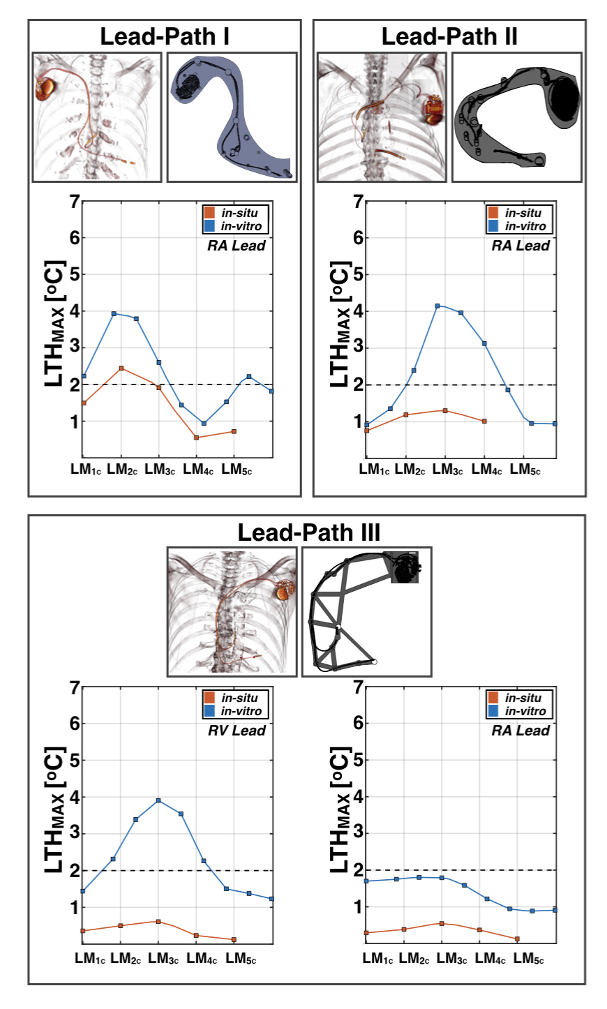
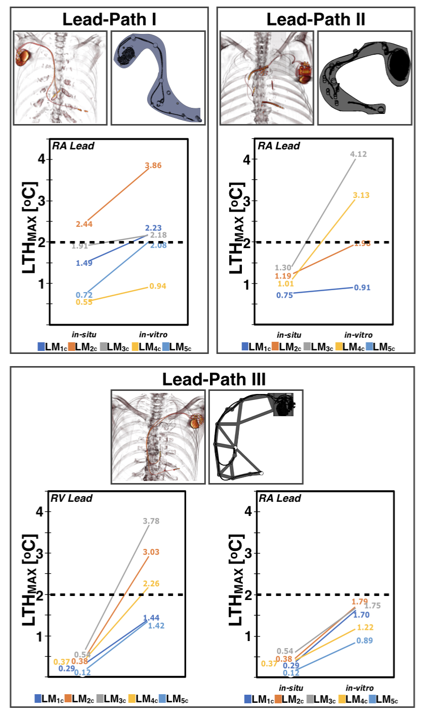
Figure 2 shows LTHmax observed for both in situ and in vitro experiments as a function of landmark. As expected, the results suggest that LTHmax depends on both the lead-path and landmark. For the three analyzed lead-paths, a similar heating pattern was observed for both in situ and in vitro configurations. LTHmax was observed to increase when the lead tip was closer to isocenter. Greater LTHmax was observed at landmarks LM2C and LM3C. A comparison of LTHmax for both configurations is shown in Figure 3. For the in situ configuration, only 1/19 (5.2%) measurements exceeded 2C. On the other hand, 13/36 (36.1%) measurements exceeded 2C for the in vitro configuration. Hence, LTHmax was observed to be greater for the in vitro configuration compared to the in situ configuration for Lead-Path I (3.9C vs. 2.4C, LM2C), Lead-Path II (4.1C vs. 1.3C, LM3C) and Lead-Path III (RV:3.8C vs. 0.5C; RA:1.8C vs.0.4C, LM3C). In general, there was no scenario in which LTH was observed to be greater for the in situ configuration compared to the in vitro configuration.Discussion
The analysis of RF-induced heating is often performed as indicated by the ASTM standard. This describes the analysis of RF-induced heating under well-controlled conditions that should represent an upper limit for RF-induced lead-tip heating. Results here suggest that the analysis of RF-induced heating for MR-unsafe cardiac AIMDs following a realistic path can induce greater temperature increase compared to an in situ configuration. Therefore, the data herein suggests that RF-heating analysis using the ASTM testing standard and phantom at 1.5T provides an upper limit on the heat that may be expected in situ. In particular, as there is no tissue perfusion for the in situ cadaver experiments, it is expected that lead-tip heat would lower in vivo.Conclusion
RF-induced heating analysis for an in vitro configuration following the ASTM testing standard at 1.5T shows greater heating than in situ configuration.Acknowledgements
This work was supported by NIH/NHLBI R21 HL127433 and the UCLA Donated Body Program.References
1. ASTM International. F2182-19 Standard Test Method for Measurement of Radio Frequency Induced Heating On or Near Passive Implants During Magnetic Resonance Imaging. West Conshohocken, PA; ASTM International, 2019. doi: https://doi-org.stanford.idm.oclc.org/10.1520/F2182-19Figures
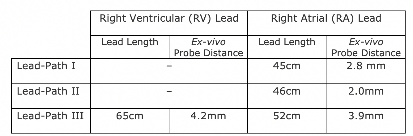
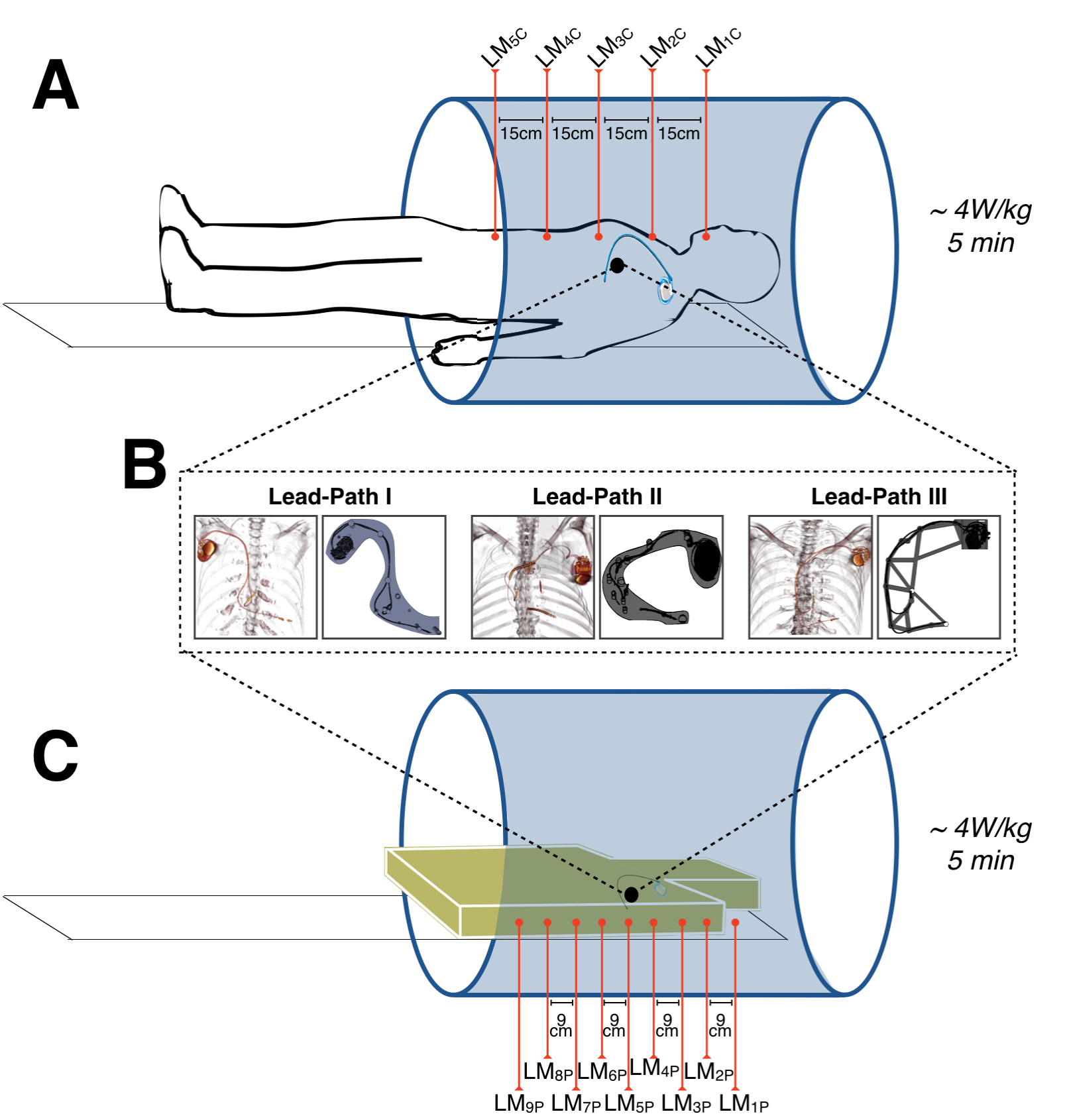
Figure 1. (A) Cadavers with previously implanted MR-unsafe cardiac-AIMDs were instrumented with temperature probes to evaluate lead tip heating (LTH) after 5-minutes of 4W/kg RF exposure at five different landmark positions.
(B) cardiac-AIMDs and leads were extracted, then repositioned using custom 3D-printed scaffolds to hold each device in a configuration matched to the in situ cadaveric location.
(C) Each cardiac-AIMD was evaluated again (5-minutes of 4W/kg RF exposure) in vitro at nine different landmarks for comparison to the results obtained in cadavers.