4188
Simultaneous RF induced heating of the human body and RF coils: Implications for tissue temperature
Xin Chen1 and Michael Steckner1
1Canon Medical Research USA, Inc., Mayfield Village, OH, United States
1Canon Medical Research USA, Inc., Mayfield Village, OH, United States
Synopsis
It is widely understood that the B1 field used in MRI can cause significant tissue heating by inducing eddy currents. Additionally, the B1 field simultaneously induces heating in all RF coils. Patient heating is indirectly constrained by SAR limits, as defined in IEC 60601-2-33, and the surface contact coil temperature limit (41°C) is defined by IEC 60601-1. An examination of the simultaneous application of both heating sources is investigated by electromagnetic and thermal modeling. Initial results suggest that while the presence of a “hot” coil elevates tissue temperatures, the two simultaneous sources of heating don’t pose a patient safety risk.
INTRODUCTION
RF burns are believed to be thermal injuries due to excessive local SAR hotspots. Thermal dose metrics like CEM431 are useful for investigating MR exposures and assessing risk to any given tissue and their specific damage thresholds. For cases of skin contact against hot surfaces, standards exist2 which characterize the contact material type, exposure time, and acceptable temperature exposure limits. 41°C is considered a safe, no justification necessary, long-term contact exposure temperature that is universally used by the MR vendors3,4. The limiting use case is the non-responsive patient strapped into a coil. The juxtaposition of both heat sources and potential consequences for patients has not been previously considered and is the focus of this abstract. Humans nor coils instantly heat on exposure to B1 fields. The general heating response of RF coils is an exponential function which rises to a steady-state temperature and the human tissue temperature rise is a more complex function of SAR and thermoregulatory responses and other cooling mechanisms (e.g. convection). EM/thermal modeling packages are presently designed to only consider the standard human exposure condition and do not consider time variable boundary conditions, such as surface contact with a coil housing. Simple conservative approximations permit an initial investigation on whether two simultaneous heat sources are a patient risk concern.METHODS
EM modeling (Sim4Life v4.4, ZMT) used 1.5T birdcage whole body transmit coil (16-rung high-pass birdcage, diameter 750mm, length 650mm. RF shield diameter 790mm, length 850mm)5,6. The unclothed human model Duke7,8 was positioned in the coil to model pelvis or wrist imaging situation (Figure 1). The coil was tuned to 64MHz and driven in QD mode with two voltage sources. Resultant RF power deposition into Duke was scaled to 4W/kg WB SAR and used as heating source for the subsequent thermal simulation using Pennes Bioheat Equation. Tissue parameters with thermo-regulated skin, fat (including subcutaneous adipose tissue) and muscle were applied.9 Thermal simulations started with 37°C initial tissue temperature and 25°C ambient air temperature. A two hour wait time (no RF heating) was applied to reach basal thermal equilibrium before the RF source was applied continuously for one hour. Thermal simulation was then repeated with hot Rx coil surfaces introduced simultaneously with RF source. The top of the abdomen and entire wrist, separately, were fitted with a completely conformal Dirichlet boundary condition with a constant temperature of 40°C, representing the coil housing (Figure 2). While an uncommon coil combination, this reflects the locations of thermal hotspots given by the simulation without hot coil and permitted one single modelling. In practice, coil housings have particular surface “hot-spots” associated with specific electronic components within the structure and are not uniformly hot for the entire surface. While this uniform surface temperature is highly conservative (e.g. near worst case), a 40°C surface temperature is only one degree below the permitted 41°C surface contact temperature. While a given coil could potentially be used on several patients in succession and thus approach its steady-state limiting temperature on later patients, typically there is opportunity for the coil to cool in the gaps between sequences and reconfiguration between patients. Thus, a constant temperature of 40°C is also considered conservative. The pelvis (with wrist at side) landmark was selected to enable a realistic maximum 4 W/kg whole body exposure scenario, for a continuous one-hour exposure. This is also considered to be a worst-case conservative exposure. The implications of an unclothed model are complex with respect to insulation that keeps body heat in, but would also insulate against the heat of the coil.RESULTS
With only RF heating peak temperature in tissue 41.2 °C was observed in abdomen (Figure 3a) and right wrist (Figure 4a). Under the simultaneous combination of 4 W/kg exposure and broad area, constant high temperature coil housing contact, temperature was further increased in the skin in contact with the coil housing, while temperature distribution in all the other tissues and the hotspot remain unchanged (Figures 3,4).DISCUSSION
While the maximum modeled temperature, with or without the warm coil housing, is marginally above the 41°C “no justification required” limit, the multiple conservative assumptions noted above suggest that the otherwise healthy patient will not be exposed to risks considered unacceptable in the relevant standards. Comparison of the “no coil” and “hot coil” results show that the hot coil certainly modifies the temperature distribution in the skin in direct contact with the coil. Other modeling results with a 2 W/kg WB SAR (not shown) showed a peak tissue temperature of 40°C. Modeling coil housing surface as a different boundary condition (e.g. 40°C constant temperature and 100 W/m^2 heat flux toward body) did not produce significant difference.CONCLUSION
An analysis of the simultaneous application of SAR induced and coil housing heat on patient safety suggests that there are no risks outside of acceptable limits.Acknowledgements
References
- Sapareto SA, Dewey WC. Thermal dose determination in cancer therapy. Int J Radiat Oncol Biol Phys 1984;10:787–800.
- ISO 13732-1: Ergonomics of the thermal environment — Methods for the assessment of human responses to contact with surfaces — Part 1: Hot surfaces
- IEC 60601-1: Medical electrical equipment - Part 1: General requirements for basic safety and essential performance
- NEMA/MITA MS-14: Characterization of RF Coil Heating in Magnetic Resonance Imaging Systems (in press)
- Murbach M, Neufeld E, Kainz W, et al. Whole-body and local RF absorption in human models as a function of anatomy and position within 1.5T MR body coil. Magn. Reson. Med. 2014; 71(2):839-845.
- Murbach M, Cabot E, Neufeld E, et al. Local SAR enhancements in anatomically correct children and adult models as a function of position within 1.5 T MR body coil. Prog Biophys Mol Biol. 2011; 107(3):428-433.
- Christ A, Kainz W, Hahn EG, et al. The Virtual Family—development of surface-based anatomical models of two adults and two children for dosimetric simulations. Phys Med Biol. 2010;55:N23.
- Gosselin M-C, Neufeld E, Moser H, et al. Development of a new generation of high-resolution anatomical models for medical device evaluation: The virtual population 3.0. Phys Med Biol. 2014;59:5287.
- Murbach M, Neufeld E, Capstick M, et al. Thermal Tissue Damage Model Analyzed for Different Whole-Body SAR and Scan Durations for Standard MR Body Coils. Mag. Reson. Med. 2014;71: 421-431.
Figures
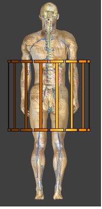
Figure 1. WB coil model with Duke for pelvis/wrist imaging
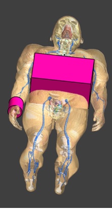
Figure 2. Boundary
conditions added to represent hot coil surface
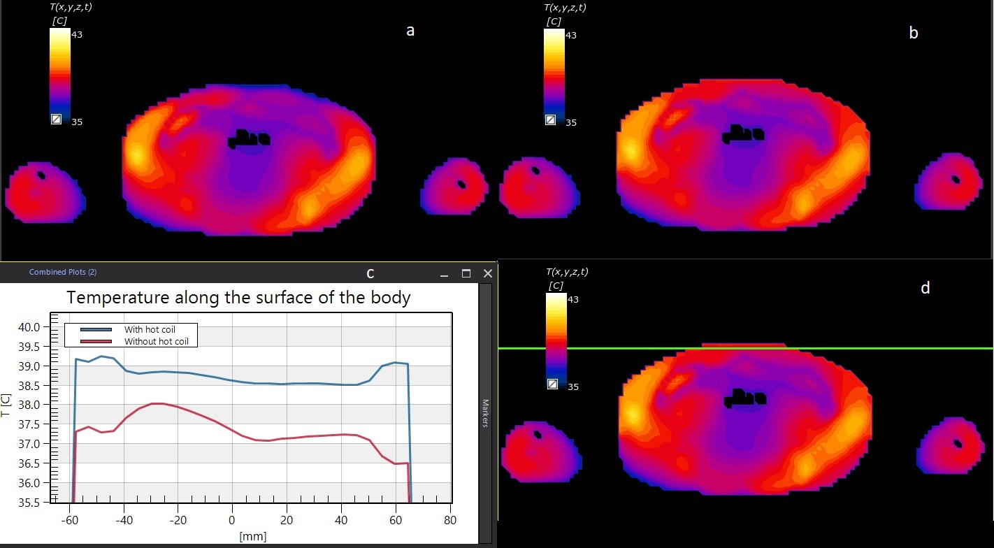
Figure 3. Tissue temperature in the abdominal slice with peak
temperature after 1 hour RF heating with 4W/kg WB SAR without (a) and with (b)
hot coil housing surface. (c) temperature is plotted along the line shown in
(d) (which is duplicate of (b)).
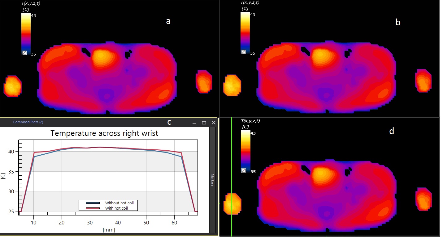
Figure 4. Tissue temperature in the pelvis slice (including wrists)
with peak temperature after 1 hour RF heating with 4W/kg WB SAR without (a) and
with (b) hot coil housing surface. (c) temperature is plotted along the line
shown in (d) (which is duplicate of (b)).