4187
Radiofrequency-Induced Risks during Magnetic Resonance Imaging: Dependence upon Birdcage Design1IT'IS Foundation, Zurich, Switzerland, 2UPV, Valencia, Spain, 3ETH Zurich, Zurich, Switzerland
Synopsis
The induced radiofrequency (RF) electrical field resulting in unwanted heating in patients with and without implants during magnetic resonance imaging (MRI) is a complex function of multiple factors which must be considered in patient risk assessment, including patient anatomy, imaging positions, RF characteristics of the implant, implant location, and MRI scanner design and scan configuration. In this paper, the dependence of the induced fields upon the birdcage design is investigated to determine the minimal range of RF body coils necessary to guarantee a comprehensive risk evaluation regarding heating and electromagnetic compatibility for any clinical MRI scanner.
Introduction
For patients undergoing magnetic resonance imaging (MRI), RF-induced heating is one of the major safety concerns, particularly for patients with long, conductive implants1. The localized RF-induced field distributions can only be reliably estimated by simulation1-4 with computational high-resolution anatomical human body phantoms, such as the Virtual Population5 placed at different landmark positions in a birdcage models. Risk assessment of patient heating requires that the range of possible induced fields experienced by patients in clinical scanners be considered.In this work, we performed a sensitivity analysis of the role of birdcage geometry and structure on the induced fields and specific absorption rate (SAR) as well as tangential E-fields (Etan) to, and deposited power (Pdep) around, representative generic active medical implants (pacemaker, and spinal cord stimulator). We then compared the results to the variation observed from patient anatomy, scan position, and scan polarization, at 64 MHz.
Method
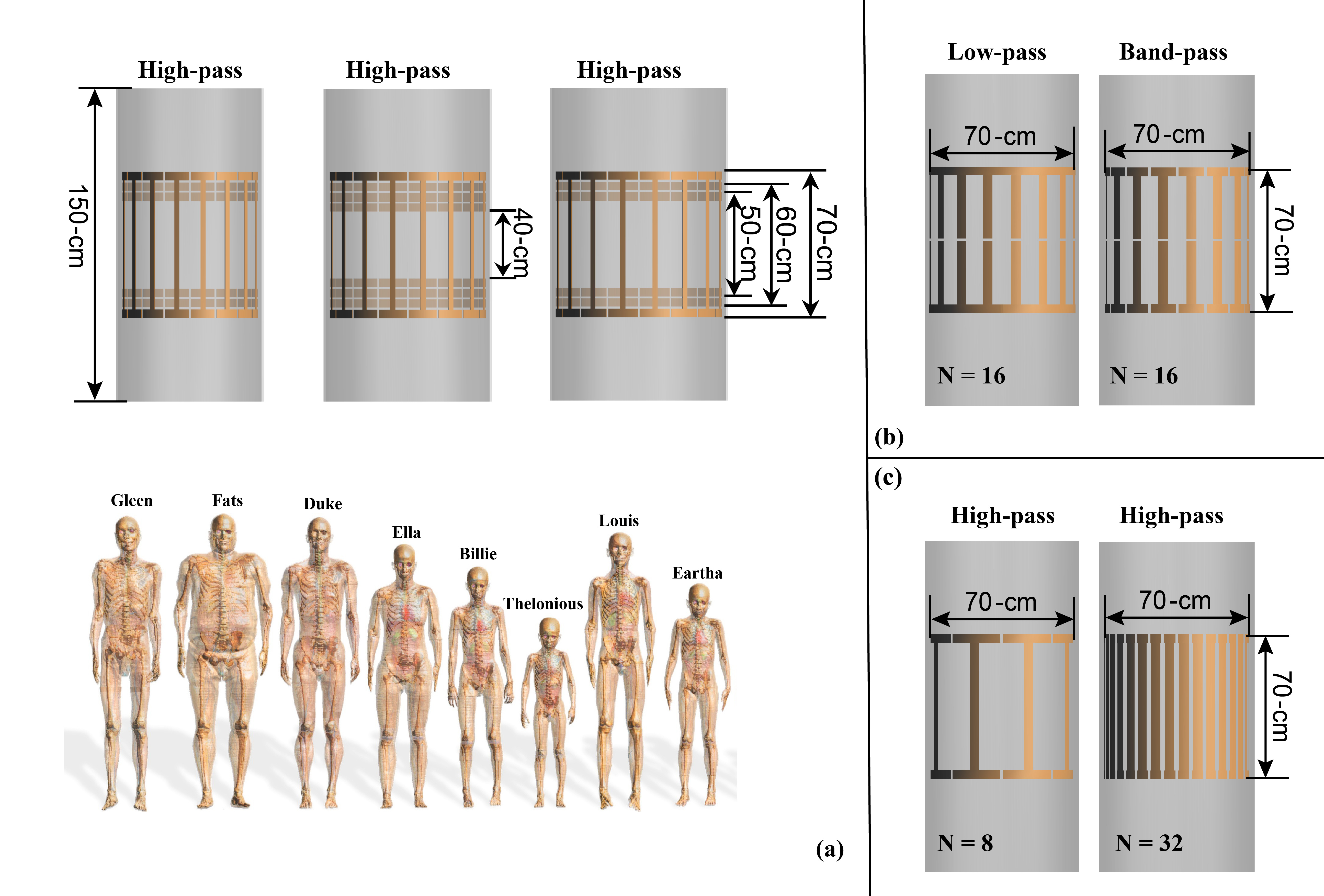
Three studies are designed. Study 1 uses the MRIxViP1.5T database6 to extract the head SAR, whole-body SAR, partial-body SAR, and B1+ for different anatomical phantoms as well as the Etan to, and Pdep around, a 40-cm long generic left-side pacemaker, for a set of ten birdcages, eight anatomical models, all imaging positions from head to foot, at circular and near-circular polarizations, as shown in Figure 1 (a). The role of birdcage diameter and length are assessed based on these results.In study 2, a set of additional birdcages were developed to estimate the sensitivity of these results to different design features, namely high-pass and band-pass birdcages fed from legs and via I/Q channels (Figure 1(b)). The patient position sensitivity was estimated by shifting model Fats 2.5 cm laterally or 10 cm dorsally.
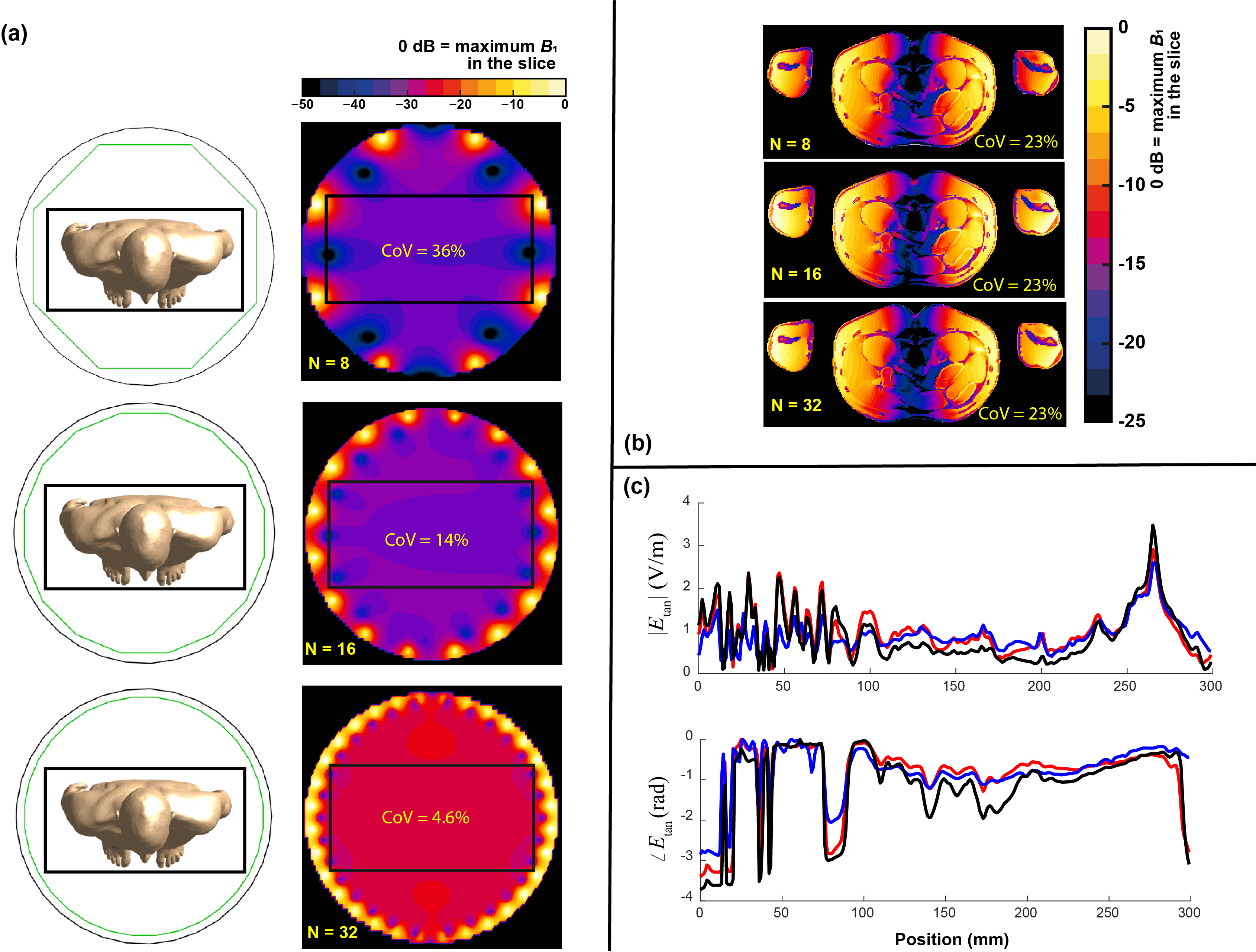
The goal of study 3 was to investigate the effect of the number of birdcage rungs on the in vivo RF-induced heating. Birdcages with length of 70 cm and bore-diameter of 70 cm with rung numbers (N) of 8, 16, and 32 were used to simulate the exposure of human model Duke at a typical thorax imaging position. The magnetic field strength and the induced in vivo electrical field distributions at the imaging position's field-of-view (FOV) are compared.
Results
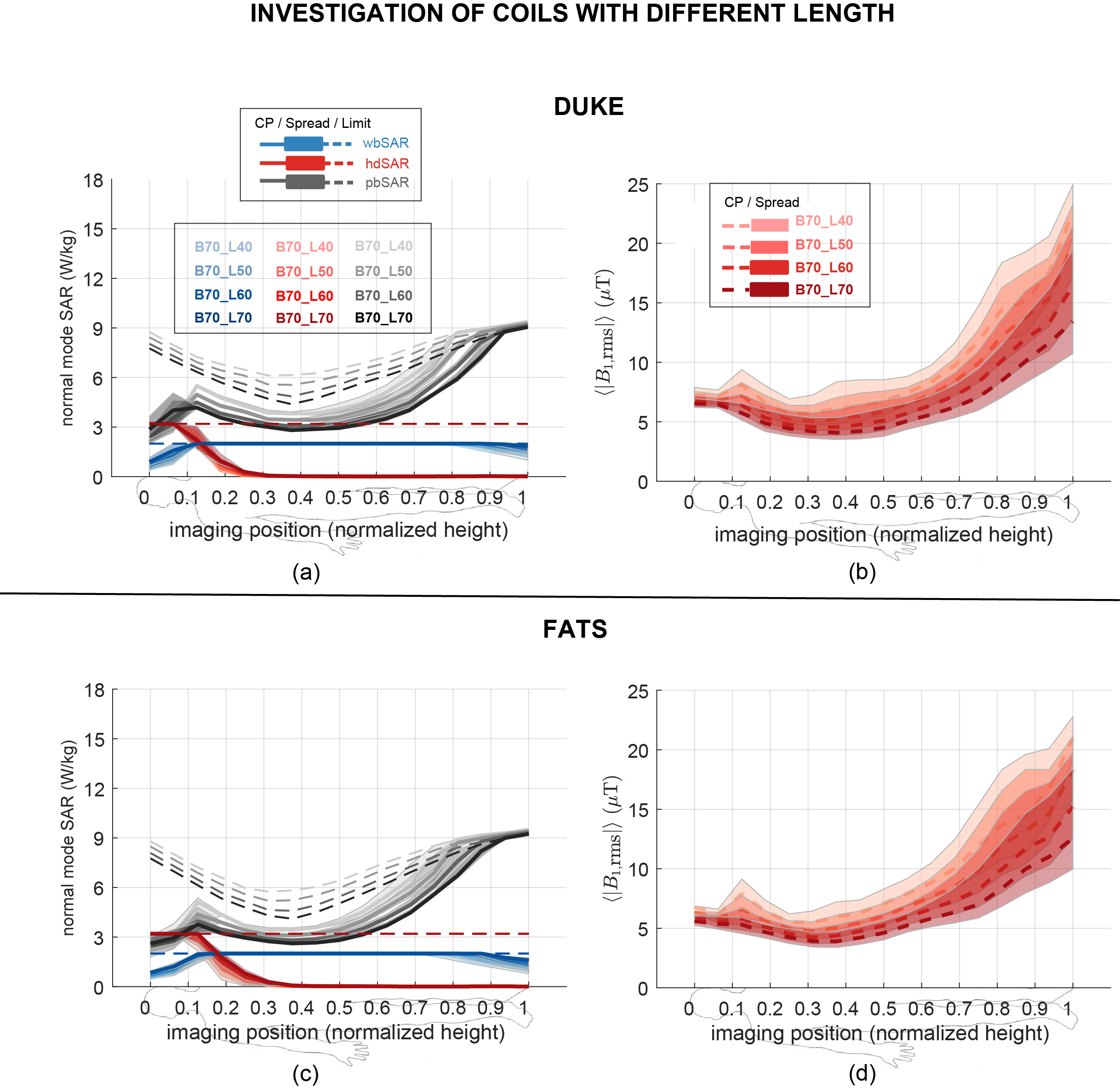
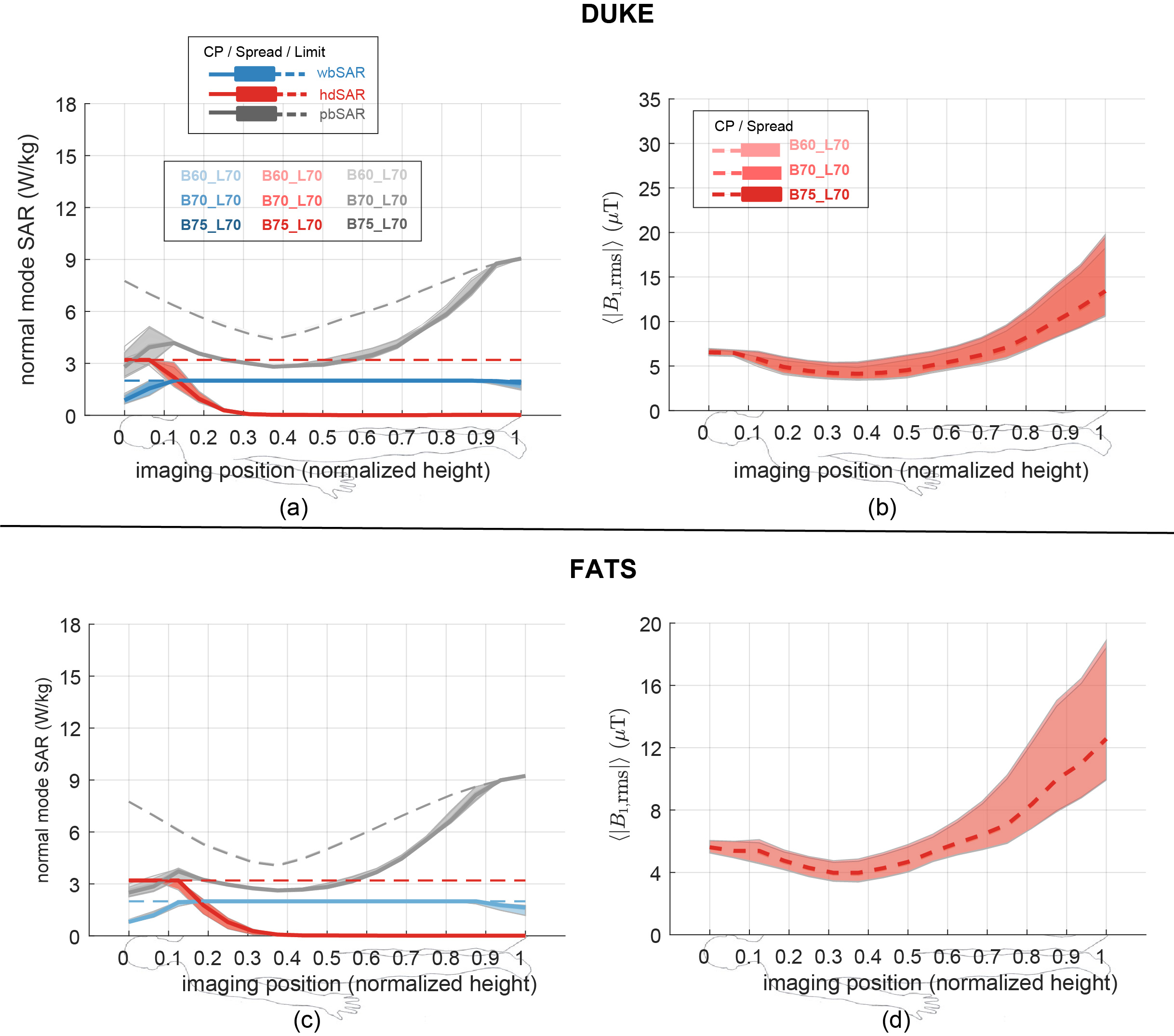
Figure 1 summarizes the exposure configurations of the birdcages and anatomical models used in this work.First, the comparison of head SAR (hSAR), whole-body SAR (wbSAR), and partial-body SAR (pbSAR) under normal operating mode7 are reported together with the maximum allowed magnetic field (B1) exposure level. Figures 2 and 3 summarize the results of study 1 for birdcage length and bore diameter sensitivity, respectively. As shown in Figure 2, the longer birdcage lengths result in larger SARs under normal operating mode, leading to lower B1 field strength at the SAR limit. In contrast, Figure 3 shows that the effect of birdcage bore-size on the in vivo SAR distribution is very limited, as birdcages with different bore-diameters give rise to effectively the same values of local SAR and wbSAR, allowing, therefore, the same B1 strength.
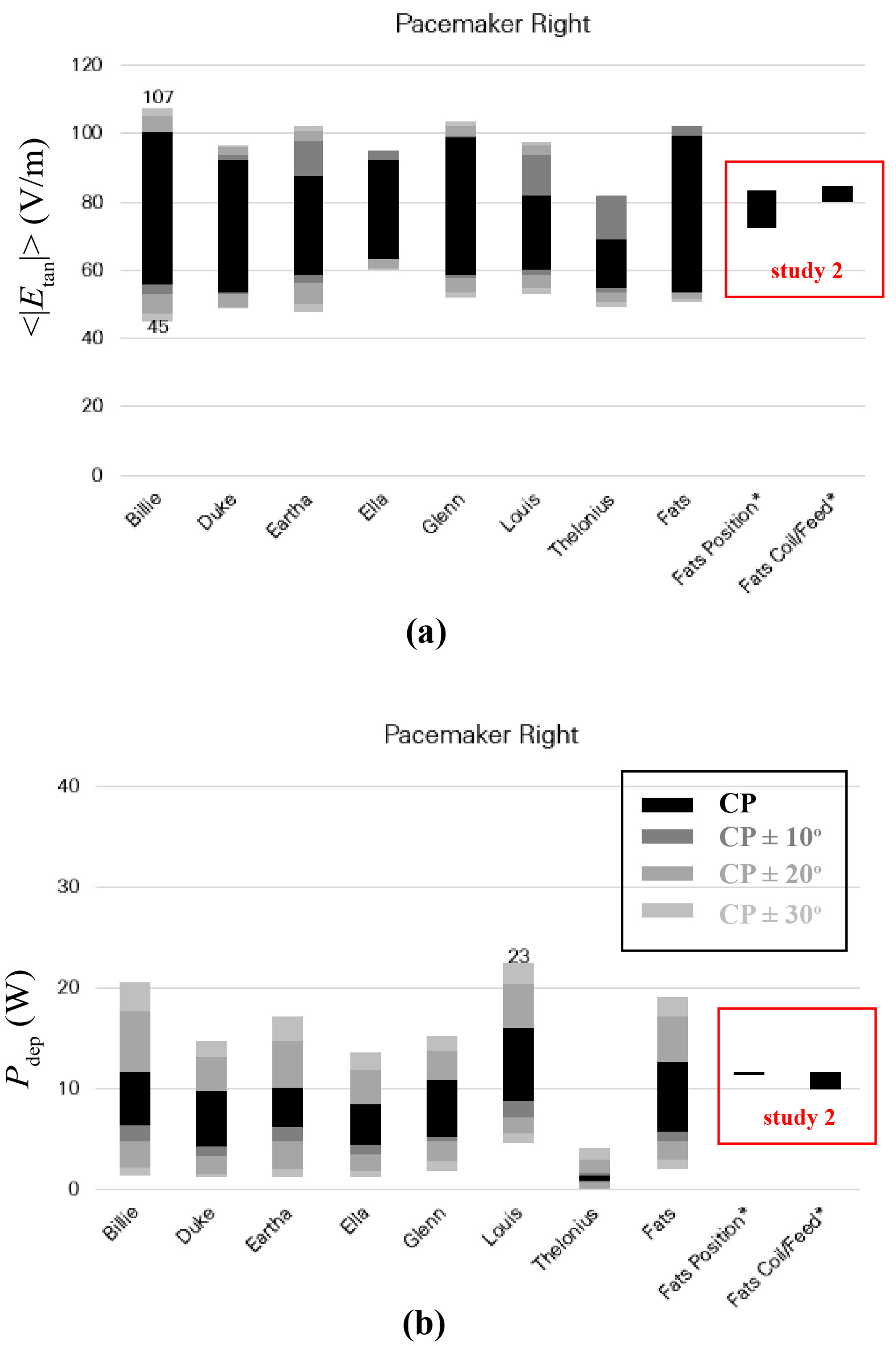
Next, the averaged Etan to, and Pdep around, a 40-cm long generic left-side pacemaker, for a set of ten birdcages, eight anatomical models, all imaging positions from head to foot, at circular and near-circular polarizations are shown in Figure 4, as well as the results from study 2.
The results of study 3 are summarized in Figure 4. Figure 4(a) shows the B1 field distribution over the FOV. Figure 4(b) shows the induced in vivo electrical field distribution of Duke, where birdcages of different rung numbers show very similar in vivo induced field distributions. These birdcages also have the same coefficient of variation (CoV) (23%) of the induced electrical field over the FOV. Similar results are observed for the simulated in vivo Etan along a typical spinal cord routing in the Duke model, as shown in Figure 4(c). The observable variations in the Etan are due to the non-ideality of the linear field polarization obtained with birdcages of varying rung numbers.
Conclusions
The evaluations performed show that birdcage diameter has only a very limited effect on the in vivo RF-induced SAR distribution, whereas birdcage length plays a critical role in determining in vivo RF-induced SAR. The sensitivity analysis of other parameters, such as high-pass vs band-pass birdcage design, birdcage current source, dorsal or lateral patient shifts, birdcage rung count, led to negligible variation compared to the dominant sources of patient anatomy, scan position, and birdcage polarization and size.Acknowledgements
No acknowledgement found.References
1. Nyenhuis JA. Park SM, Kamondetdacha R, et al. MRI and implanted medical devices: Basic interactions with an emphasis on heating. IEEE Trans Device Mater Reliab 2005;5(3):467–479.
2. Muranaka H, Horiguchi T, Usui S, et al. Dependence of rf heating on SAR and implant position in a 1.5 T MR system. Magn Reson Med Sci 2007;6(4):199-209.
3. Kangarlu A, Schellock F, and Chakeres D. 8.0-tesla MR system: temperature changes associated with radiofrequency-induced heating of a head phantom.
4. Murbach M, Neufeld E, Capstick M, et al. Virtual population-based assessment of the impact of 3 Tesla radiofrequency shimming and thermoregulation on safety and B1+ shimming. Magn Reson Med 2016;76:986-997.
5. Gosselin M-C, Neufeld E, Moser H, et al. Development of a new generation of high-resolution anatomical models for medical device evaluation: the Virtual Population 3.0. Phys Med Biol 2014;59:5287–5303.
6. IT'IS. https://itis.swiss/virtual-population/explib/overview/
7. IEC. IEC standard 60601-2-33. Medial electrical equipment - particular requirements for the basic safety and essential performance of magnetic resonance equipment for medical diagnosis. 2010.
Figures