4180
Impact of a neighboring device on in vitro lead heating measurements
Louai Aldayeh1, Mizan Rahman1, and Ross Venook1
1Boston Scientific, Valencia, CA, United States
1Boston Scientific, Valencia, CA, United States
Synopsis
For patients with more than one MR Conditional implant, it is unclear how to choose appropriate scanning conditions, as interactions between neighboring devices are generally not well characterized. This work assesses how lead electrode heating of an IPG/lead based system can be impacted by the presence of a neighboring IPG/lead based system at moderate distances (~15cm). The results demonstrate that lead electrode heating can either decrease or increase, depending on the relative location of the neighboring device. The potential implication is that established conditions for MR safety of one implant may not be appropriate in the presence of neighboring implant.
INTRODUCTION
Some patients have multiple MR Conditional active implantable devices (e.g., a cardiac pacemaker and a deep brain stimulator (DBS); a spinal cord stimulator (SCS) and a deep brain stimulator; or multiple devices of the same type). In these scenarios, the MRI exposure safety limits of the two systems may not be equivalent, and prescribing appropriate scan conditions can be challenging for clinicians. Previous work has investigated potential complicating factors of testing induced heating in implantable systems, including abandoned leads with different proximal capping [1], effects of partial implantation [2], and effects of multiple adjacent tissue simulating media [3]. This work investigates the potential for second-order interactions between neighboring devices that can impact RF-induced heating measurements and safety assessments.METHODS
Using established measurement techniques, with an ASTM phantom in a 1.5T birdcage, and high conductivity medium (HCM) gel [4], two separate implantable pulse generator (IPG) systems (each having: one IPG, one 55cm lead extension and one lead) were tested for lead electrode heating using fiber optic temperature probes (Neoptix, Qualitrol, Fairport, NY). The two implants were mounted in the ASTM phantom as illustrated in Figure 1, with a consistent 15cm parallel distance along the majority of their trajectories.Three system setups/lead routings were tested:
- One single-lead IPG system (with 55cm lead extension and 30cm lead), on either the right or left side of the phantom. See the gray colored scenarios in Figure 2.
- One dual-lead IPG system (with two 55cm lead extensions and one each of 30cm & 45cm leads), on either the right or left side of the phantom. See the blue colored scenarios in Figure 2.
- Two separate single-lead IPG systems (each with one IPG, one 55cm lead extension and one 30cm lead). See the orange colored scenario in Figure 2.
All tests were done under nominally equivalent exposure conditions, as measured by an E-field probe (EX3DV4, Speag, Zurich, Switzerland) at a consistent high-SNR location at a distance from any test objects (“E-field Ref” red dot in Figures 1 and 2).
RESULTS
All heating results are reported (in normalized units) in Figures 3 and 4. Figure 3 reports all measurement results of the left side of the ASTM phantom. Figure 4 reports all measurement results of the right side of the ASTM phantom. The three groups of results are: left-group for blue layout scenario (one dual-lead IPG system), center- group for orange layout scenario (two separate single-lead IPG systems), and right-group for the gray layout scenario (one single-lead IPG system).DISCUSSION
From Figure 3, the left ASTM side results show that heating of the left-side system by itself (gray layout) was higher compared to when another system was mounted 15 cm away (orange layout). As a check point for one IPG with dual lead mounted (blue layout), heating is even lower than both comparison scenarios.From Figure 4, the right ASTM side results show that heating of the right-side system by itself (gray layout) was lower compared to when another system was mounted 15 cm away (orange layout). As a check point for one IPG with dual lead mounted (blue layout), heating is even lower than both comparison scenarios. For an estimate of percentage increase of heating for a single-lead system with or without a neighboring system, Figure 5 shows a 10% increase in heating with 5cm distal array separation and 26% increase with 13cm distal array separation.
As shown, implants mounted on the left ASTM side exhibited results that are different from implants mounted on the right ASTM side. These differences are attributed to various factors, such as lead/IPG routing as well as birdcage fields that depend on polarization [5].
The overall results show that lead heating of an IPG/lead based implant can either increase or decrease in the presence of a neighboring system that is up to 15cm away.
CONCLUSION
Implant lead heating measurements of IPG/lead based systems are impacted (can increase or decrease) by the presence of another implant nearby. MR Conditional safety evaluations and labeling should consider such scenarios appropriately.Acknowledgements
No acknowledgement found.References
- Langman DA., et al. Pacemaker lead tip heating in abandoned and pacemaker-attached leads at 1.5 Tesla MRI. J Magn Reson Imaging. 2011 Feb;33(2):426-31.
- Zeng Q., et al. MRI induced heating for fully implanted, partially implanted and minimally implanted medical electrode leads. International Conference on Electromagnetics in Advanced Applications (ICEAA), 2015.
- Kozlov M. et al. Influence of the second surrounding tissue on radio frequency induced power deposition. IEEE International Symposium on Antennas and Propagation & USNC/URSI National Radio Science Meeting, 2016.
- ASTM F2182-19. Standard Test Method for Measurement of Radio Frequency Induced Heating On or Near Passive Implants During Magnetic Resonance Imaging
- Nordbeck P. et al., Spatial distribution of RF-induced E-fields and implant heating in MRI. Magn Reson Med. 2008 Aug;60(2):312-9.
Figures
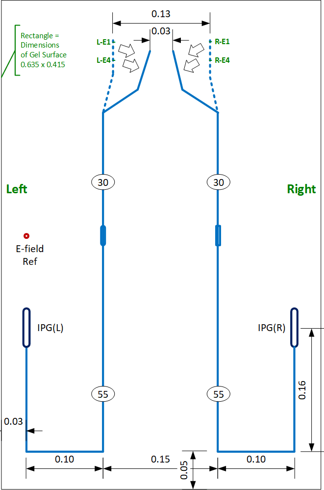
Figure 1: The two single-lead
DBS implants were mounted in the ASTM phantom as illustrated. This is labeled
later for comparison purposes “orange layout”.
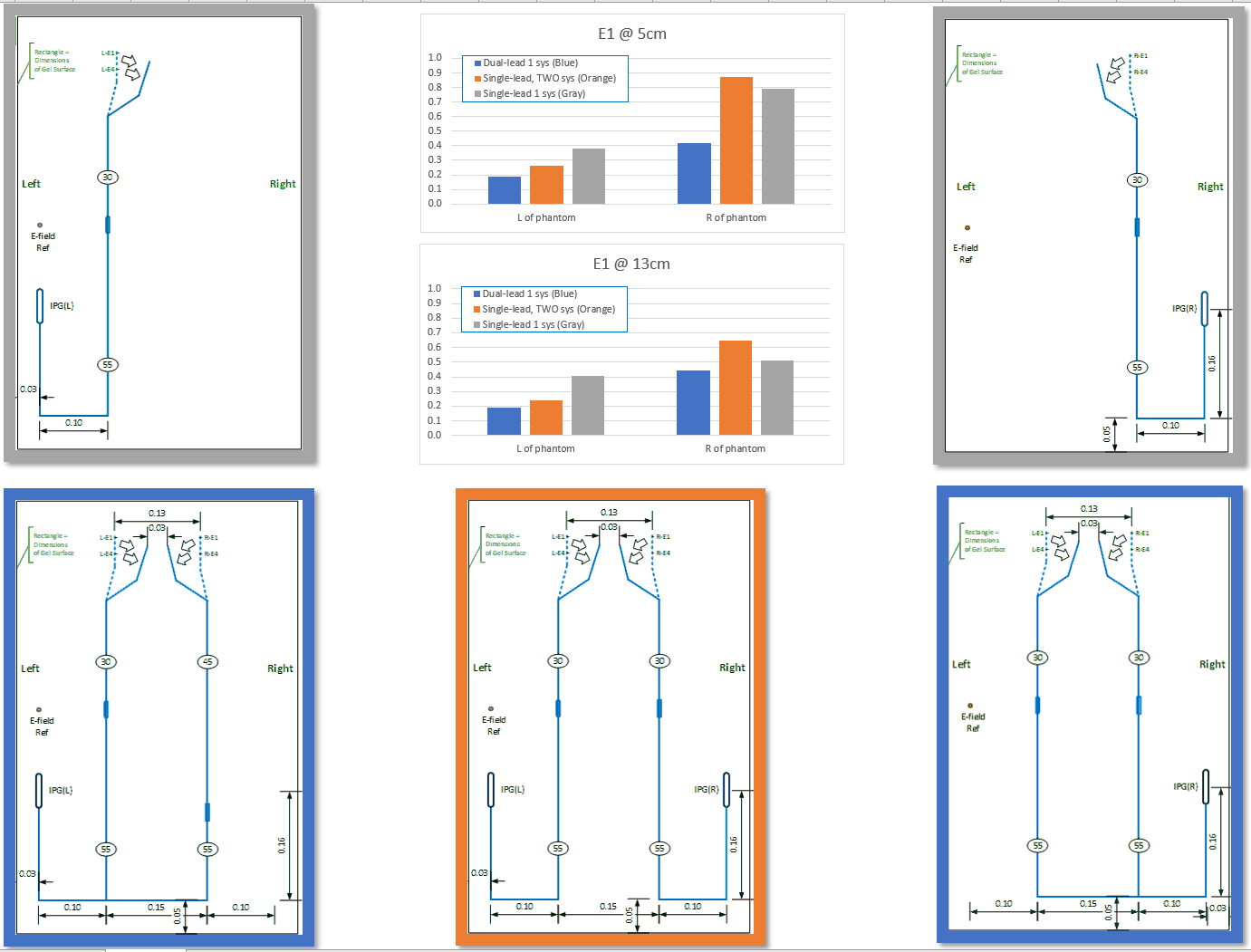
Figure 2: The 5 scenarios of
testing. (1) Upper left: single-lead one system, (2) lower left: dual-lead one
system, (3) Upper right: single-lead one system, (2) lower right: dual-lead one
system, and (5) lower center: two systems, each single-lead.
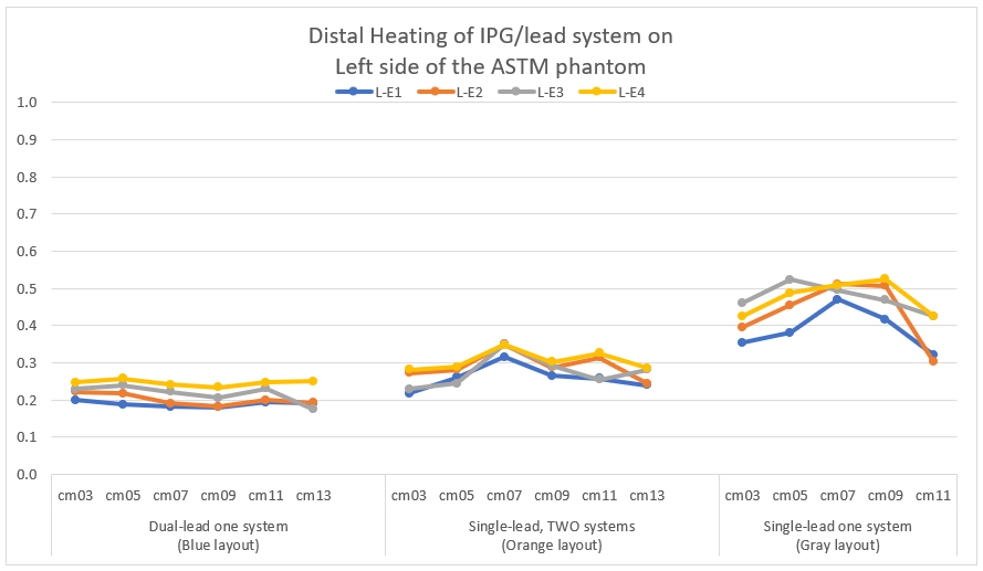
Figure 3: All normalized
heating measurement results of the left ASTM side, with cm03-cm013 indicating
position of the distal contact array
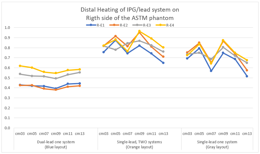
Figure 4: All normalized
heating measurement results of the right ASTM side.
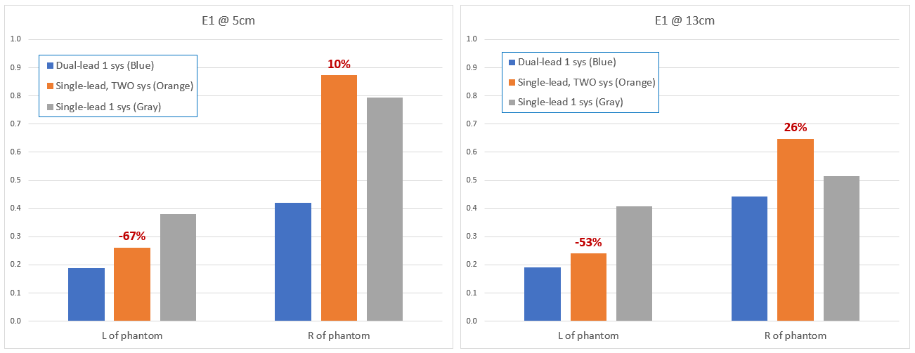
Figure 5: Summary of the
results of Figure 4 for Electrode 1 (E1) at 5cm distal array separation (left),
and at 13cm distal array separation (right).