4178
Parametric analysis of gradient-induced heating in simplified models of metallic implants
Alessandro Arduino1, Umberto Zanovello1, Luca Zilberti1, Mario Chiampi1, and Oriano Bottauscio1
1INRiM, Torino, Italy
1INRiM, Torino, Italy
Synopsis
MRI safety for patients carrying metallic implants, whose prevalence grows continuously, has become a matter of concern, so that risk assessment for passive implanted medical devices is important for both radiologists and implant manufacturers. A wide analysis of parameters influencing the thermal effects of Gradient Coil fields is here performed. Results show that it seems possible to identify some general rules related to this cause of heating, also in view of future standardized approaches.
Introduction
MRI safety for patients carrying metallic implants, whose prevalence grows continuously, has become a matter of concern. A clear definition of the risk assessment for passive implanted medical devices, ranging from orthopaedic components up to small surgical implants, is important for both radiologists and implant manufacturers. For such a purpose, an European project within the framework of the metrology community (EURAMET) is currently on-going to define measurement/computation procedures to demonstrate compliance with MRI safety regulations1.This paper focuses on thermal effects of Gradient Coil (GC) fields, which have received attention in recent scientific literature2,3,4,5,6. The eddy currents induced by the switching GC fields inside the metallic implant heat it up increasing the surrounding tissues temperature through diffusion. Since the GC heating mechanism involves many factors, like the implant shape, size and physical properties, the MRI magnetic field spatial distribution and the MRI sequence characteristics, a wide parametric analysis under simplifying assumptions is needed to discriminate influencing factors.
Methods
The temperature increase is estimated by numerical simulations, based on a computational tool that integrates the computation of eddy currents and power deposition in the metal with the thermal diffusion towards surrounding tissues. This computational scheme, previously validated against laboratory experiments7, is suitable to take into account the time waveforms of most used MRI sequences.Because of the large variability of metallic implants, a simplified shape is adopted in the analysis. Spheres with radii from 5 mm to 50 mm and spheroids with radii of 20 mm and 40 mm and longitudinal semi-axis varying from 5 mm to 120 mm are considered. With reference to the implant alloys, the electrical conductivity is varied from 0.1 MS/m up to 1.5 MS/m.
The implant models are surrounded by homogenous phantoms, whose thermal properties correspond to muscle or bone in the IT’IS database8 or a suitable gel (thermal conductivity 0.5 W/(m∙K), heat capacity 3700 J/(kg∙K), density 1100 kg/m3).
By adopting the simplified standardized approach of ISO_TS_109749, a continuous, symmetrical, trapezoidal GC signal is used, whose rising time ts varies from 0.2 ms to 1 ms. The trapezium flat top, with duration ranging from 0 to 3 ms, is set to the realistic value of 30 mT/m. The analysis is performed applying a uniform magnetic flux density of 3 mT, verifiable value within tubular scanners in positions where the implant can be realistically located.
Results
More than 150 simulations are performed, by combining the parameters variability. In all simulations, the GC is continuously supplied for 1800 s. The maximum local power density, the total power, and the maximum temperature rise after 300 s and 1800 s are recorded. The results have a quadratic dependence with respect to the gradient intensity.The effect of the implant shape is sketched in Fig. 1 for different GC signals, electric conductivity of 1 MS/m and a phantom having muscle properties. The spheroid axis is oriented along the magnetic field direction.
In an elongated implant, the B-field direction affects the power deposition, as sketched in Fig. 2, where the field is oriented along the spheroid axis, the perpendicular direction or an intermediate axis.
The influence of the sequence parameters is summarized in Fig. 3. In Fig. 4, the role of the electrical conductivity of the implant metal is investigated.
Finally, the correlation between the temperature increase and the ratio between the total power and the external surface of the implant is shown in Fig. 5.
Discussion
The implant size strongly affects the heating: assuming a given value of the gradient amplitude, a minimum sphere size can be determined under which the heating effects can be disregarded. Precisely, for the considered amplitude, the heating, after 1800 s, is always lower than 1 K for spheres with radius smaller than 15 mm (Fig. 1).In case of elongated implants, the power is lower when the field is directed along the main axis, whereas it is higher if the field is along the transversal direction (Fig. 2).
At the increase of the sequence rising time, power and temperature always reduce, whereas the dependence on the flat duration is non-monotonic (Fig. 3).
The increase of the electrical conductivity determines an increase of the dissipated power and the maximum temperature up to a given size. When skin effect plays a significant role, the behavior is no longer monotonic (Fig. 4).
Fig. 5 shows a linear dependence of the maximum temperature with respect to the ratio between the total power and the external surface, which holds independently of the considered parameters values, especially for the longest duration.
The maximum variation between maximum temperature increase considering muscle and gel phantom is lower than 10 %. Higher variation (up to 50 %) are found when using the properties of bone.
Conclusion
The parametric analysis gives some useful hints about the parameters that mostly affect the heating of implants due to GC fields. It seems possible to identify some general rules, also in view of a standardized approach. A future extensive work will be focused on the application of these rules to realistic implants in order to clarify on the reliability of a possible standardized approach.Acknowledgements
The results here presented have been developed in the framework of the 17IND01 MIMAS Project. This project has received funding from the EMPIR Programme, co-financed by the Participating States and from the European Union’s Horizon 2020 Research and Innovation Programme.References
- EURAMET - JRP 17IND01 MIMAS, “Procedures allowing medical implant manufacturers to demonstrate compliance with MRI safety regulations”, https://www.ptb.de/mimas/home.
- IEC 60601-2-33: Particular requirements for the safety of magnetic resonance equipment for medical diagnosis.
- Graf H, Steidle G, Schick F Heating of Metallic Implants and Instruments Induced by Gradient Switching in a 1.5-Tesla Whole-Body Unit. J Magn Reson Im. 2007;26:1328–1333.
- El Bannan K, Handler W, Chronik B, et al. Heating of Metallic Rods Induced by Time-Varying Gradient Fields in MRI. J Magn Reson Im. 2013, 38:411-416.
- Zilberti L, Arduino A, Bottauscio O, et al. The Underestimated Role of Gradient Coils in MRI Safety. Magn Reson Med. 2017, 77:13-15.
- Bruehl R, Ihlenfeld A, Ittermann B. Gradient heating of bulk metallic implants can be a safety concern in MRI. Magn Reson Med. 2017, 77:1739-1740.
- Arduino A, Bottauscio O, Brühl R, et al. In silico evaluation of the thermal stress induced by MRI switched gradient fields in patients with metallic hip prosthesis. Phys Med Biol. 2019 https://doi.org/10.1088/1361-6560/ab5428.
- IT’IS Database for thermal and electromagnetic parameters of biological tissues. 2016. [Online]. Available: http://www.itis.ethz.ch/database.
- ISO_TS_10974_2018(E) - Assessment of the
safety of magnetic resonance imaging for patients with an active implantable
medical device.
Figures
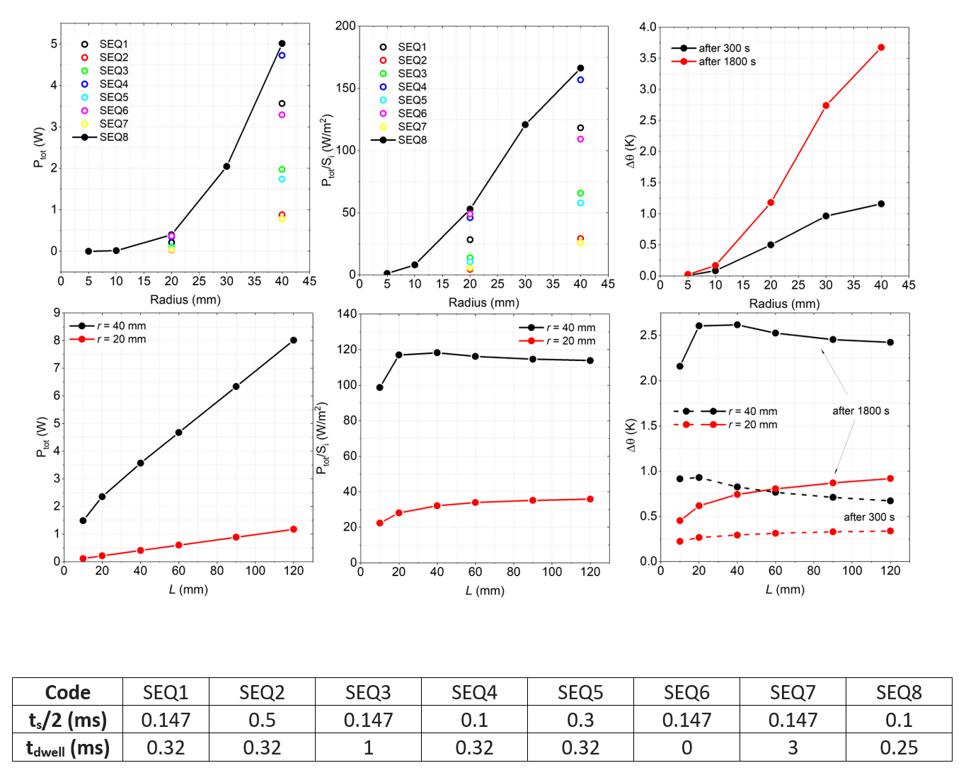
Effect of implant shape on total power deposed
in metal Ptot, ratio of Ptot to external surface Si
and maximum temperature rise Δθ.
Spheres in upper row: Ptot and Ptot/Si versus
radius r for all sequences and Δθ for SEQ8. Two spheroids in next row: Ptot, Ptot/Si
and Δθ versus semi-length of the rotational axis L
with SEQ1 sequence. All implants (1 MS/m electric conductivity) are in muscle
phantom. The table identifies the sequences through rising time ts and
flat level duration tdwell.
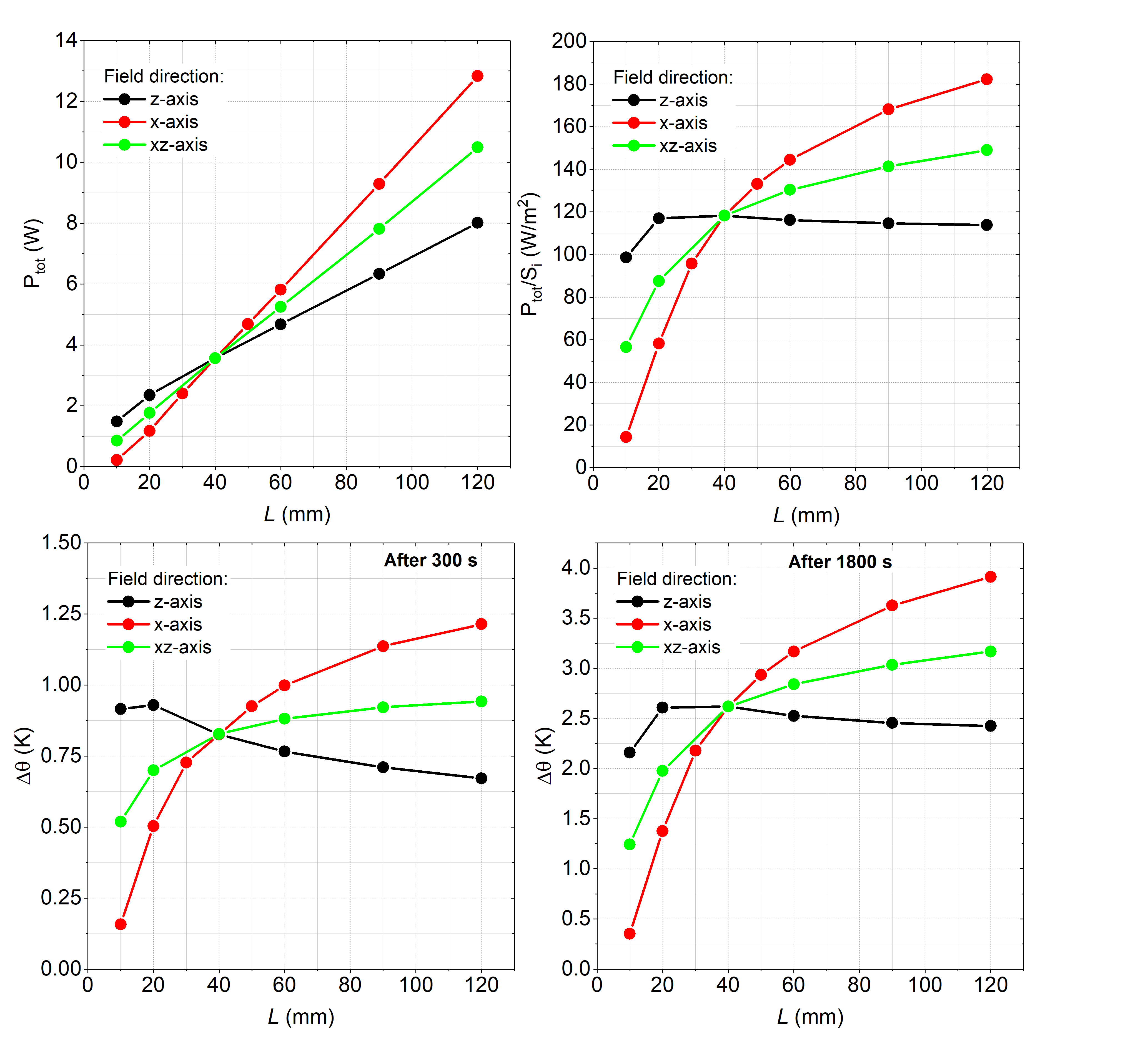
Effect of magnetic field direction on total
power dissipated in the implant Ptot, ratio of Ptot to
external surface Si and maximum temperature rise Δθ after 300 s and 1800 s. The implants are spheroids in muscle phantom, with 1
MS/m electric conductivity, radius of 40 mm and different semi-length of the
rotational axis L, exposed to SEQ1. The spheroids longitudinal direction is parallel
to the z-axis.
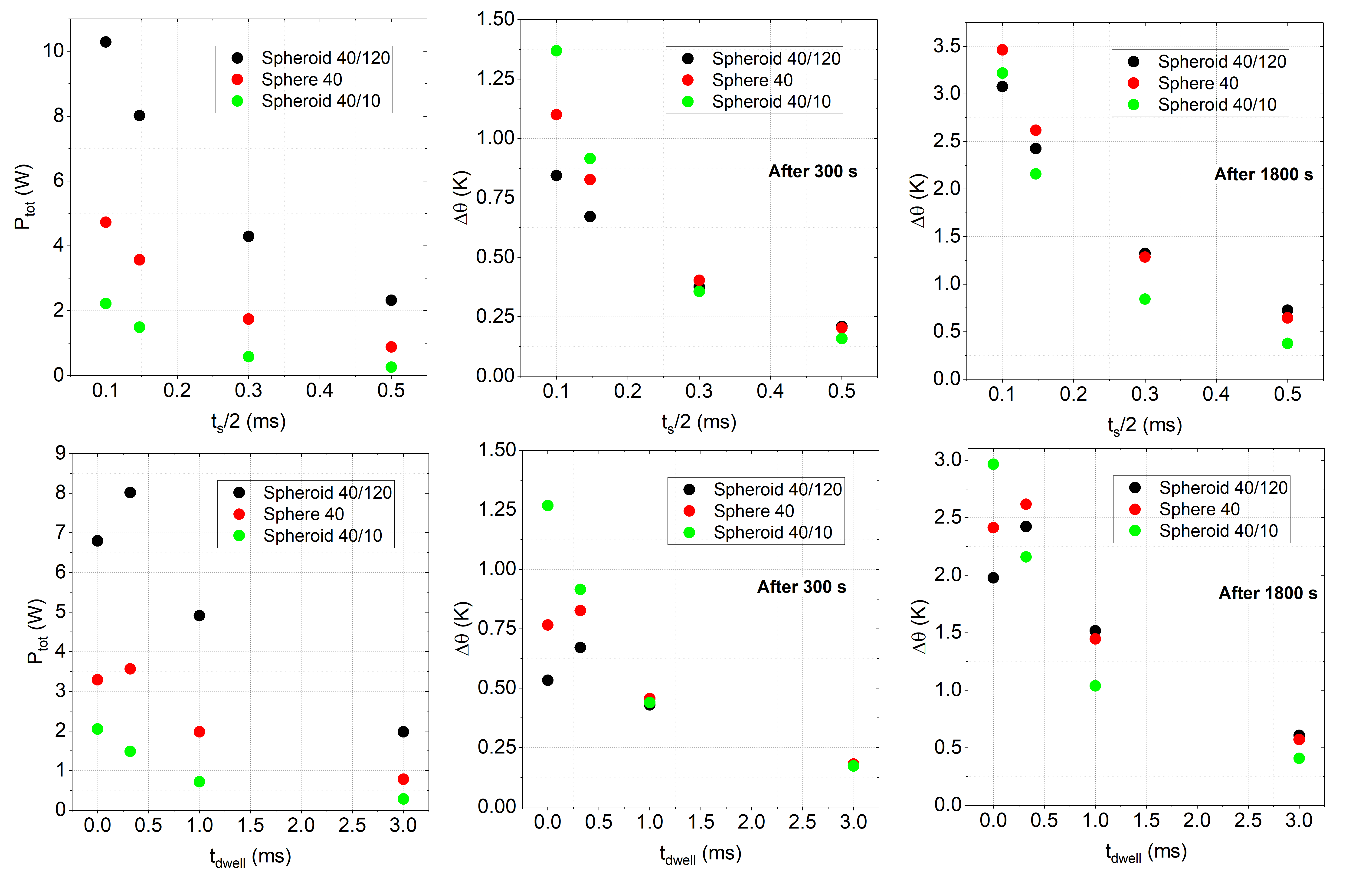
Effect of the sequence parameters on total power
dissipated within the implant Ptot and maximum temperature rise Δθ after 300 s and 1800 s for three implants with 1
MS/m electric conductivity embedded in muscle phantom. Upper row: results for
different rising times and a fixed flat top time tdwell = 0.32 ms.
Lower row: results for different flat level duration and a fixed rise time ts/2
= 0.147 ms.
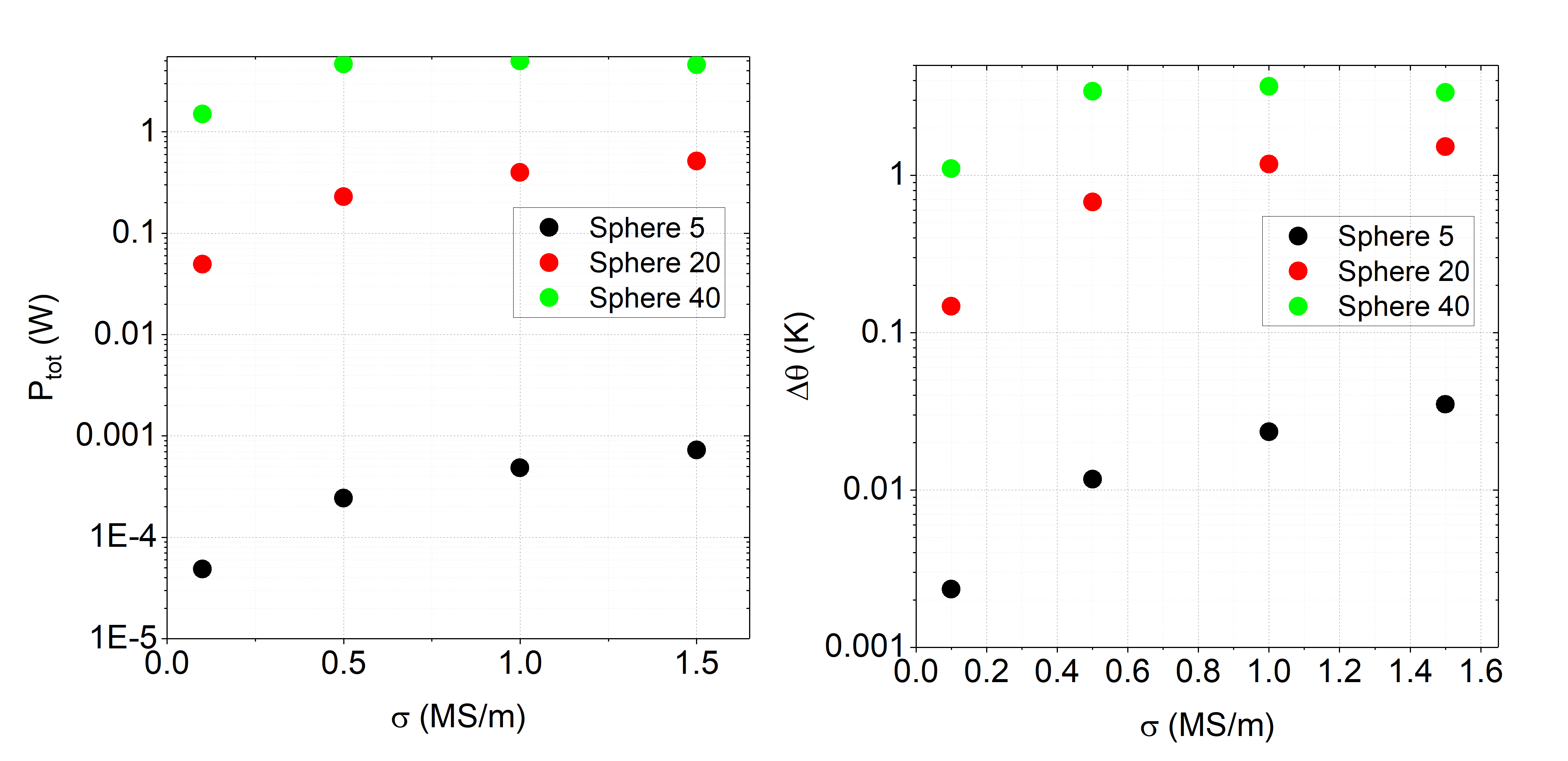
Effect of electrical conductivity σ of
the implant material on total power dissipated within the implant Ptot
and maximum temperature rise Δθ after
1800 s for three spheres embedded in muscle phantom and exposed to sequence
SEQ8.
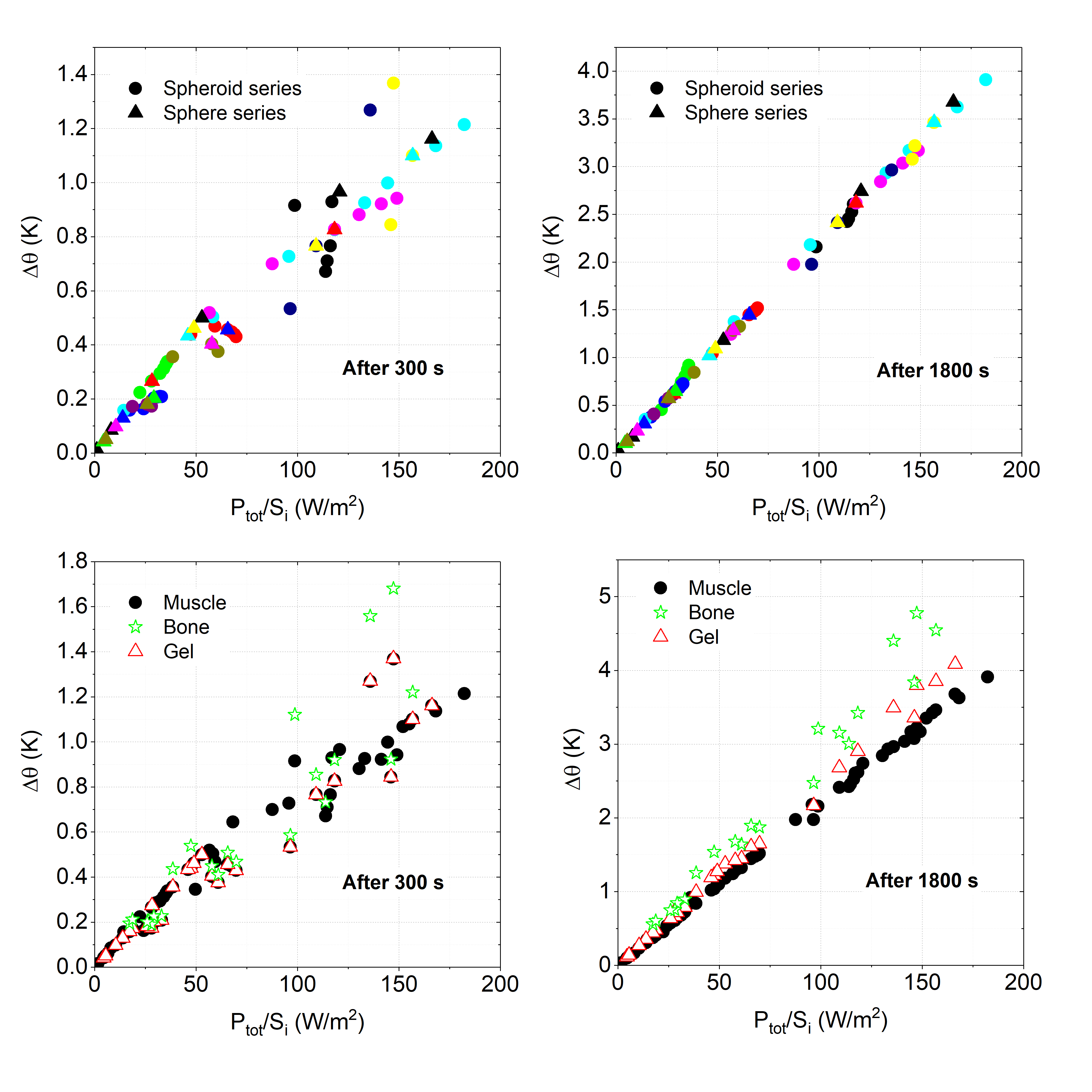
Correlation between maximum temperature rise Δθ after 300 s and 1800 s
and ratio of total power dissipated in the implant to
external surface Ptot/Si. The upper diagrams collect
results with the muscle phantom and the symbols identify sets of simulations
performed on models that differ for a single parameter variation (shape,
sequence, implant material). The lower diagrams group the results for different
phantom properties.