4177
Effect of device configuration and patient’s body composition on RF heating of deep brain stimulation (DBS) implants during MRI1Northwestern University, Chicago, IL, United States, 2Northwestern Medicine, Chicago, IL, United States
Synopsis
Off-label use of MRI in patients with DBS implants has been reported at 3T, relying only on safety tests in ASTM phantoms and with limited configurations. We constructed a multi-compartment anthropomorphic phantom consisting of brain, skull and body tissue, and measured RF heating of a fully implanted DBS system with various configurations during MRI at 1.5T. We found an 89-fold variation in RF heating depending on DBS device configuration. Simulating subcutaneous fat (as happens in obese patients) by adding a thin layer of oil to cover the upper face of the IPG increased RF heating by 3-fold in some configurations.
Introduction
Off-label use of MRI in patients with deep brain stimulation (DBS) implants is increasingly reported at 3T [1, 2], relying on safety assessments in ASTM-like phantoms (i.e., box shaped, single material) and limited number of DBS device configurations. This is alarming for two reasons: first, as RF heating is highly sensitive to implant’s configuration and its orientation with respect to MRI electric field [3-16], and as trajectory of DBS leads is substantially variant among patients [9], basing safety inferences on few tested configurations can expose large number of patients to unreasonable risks. Second, recent studies have reported up to 10-fold discrepancy in calculated SAR around implants in the ASTM box versus human body models [17].Here we report results of RF heating of a fully implanted DBS device with eight different clinically relevant configurations implanted in a multi-compartment anthropomorphic phantom consisting of brain-mimicking tissue, skull, and human-shaped head and torso. We observed an 89-fold variation in RF heating (from 0.14°C to 12.5°C) based on body composition and DBS device configuration. Our results suggest that a paradigm shift toward using multi-tissue anthropomorphic phantoms is necessary in MRI RF safety assessments.Methods
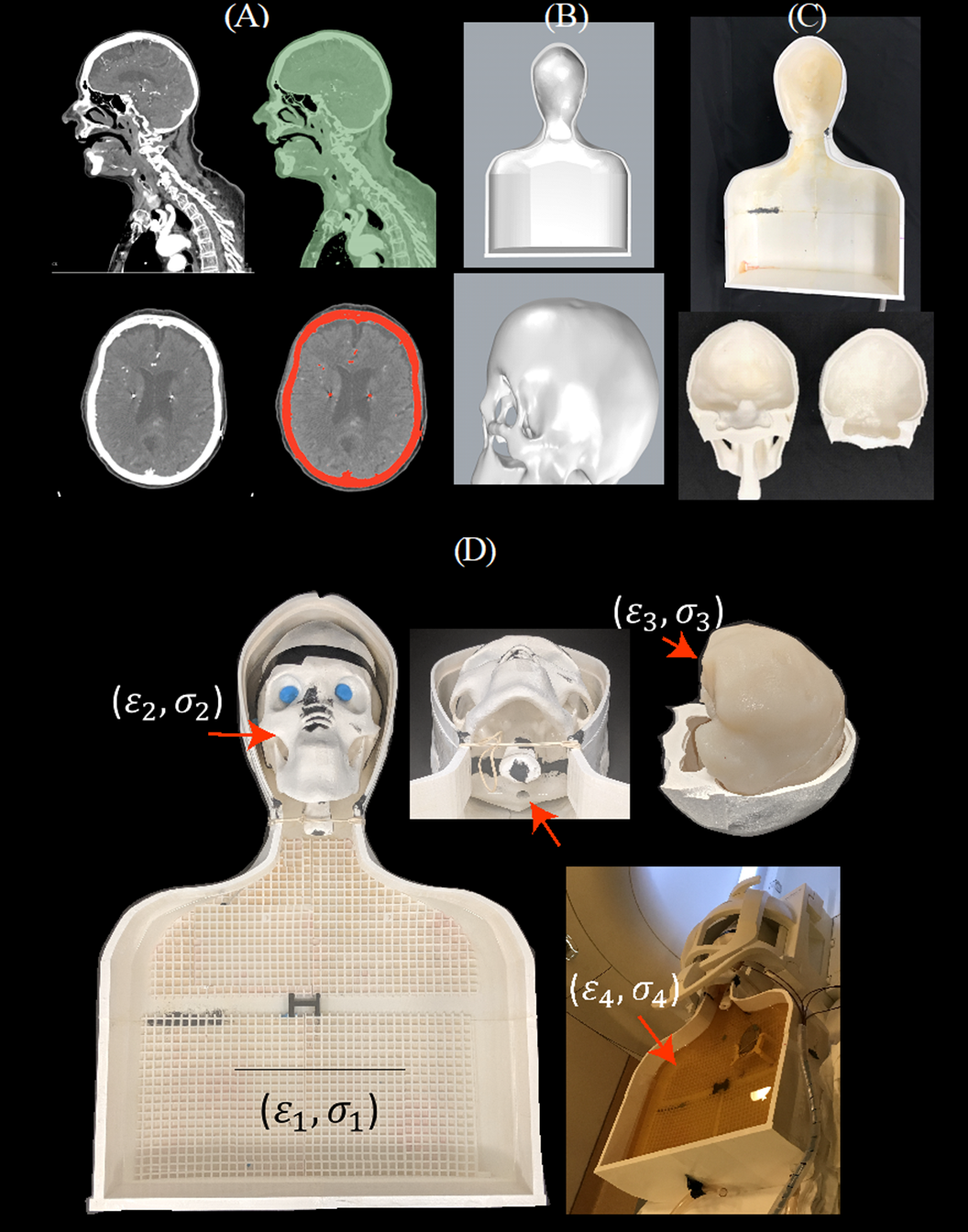
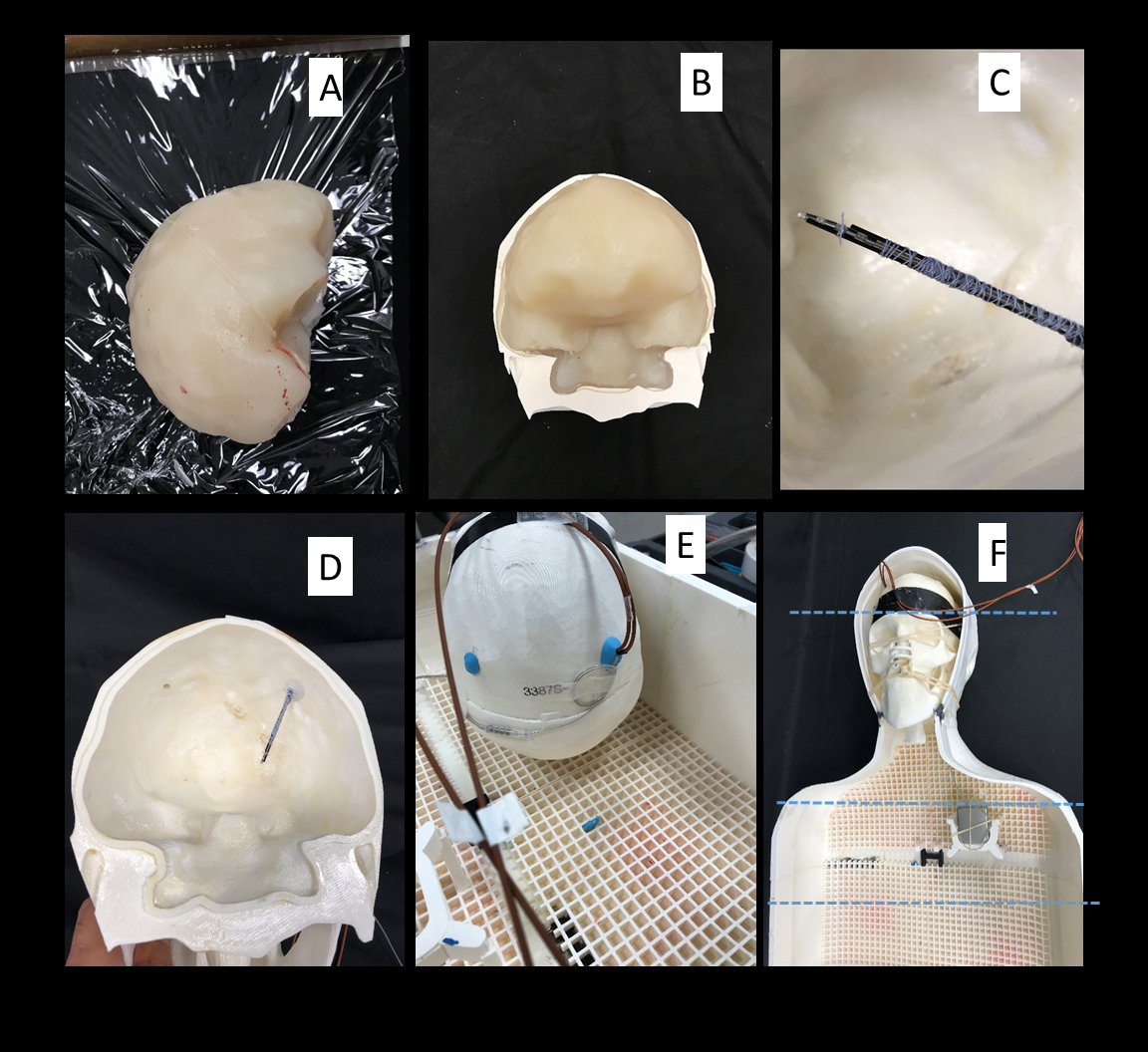
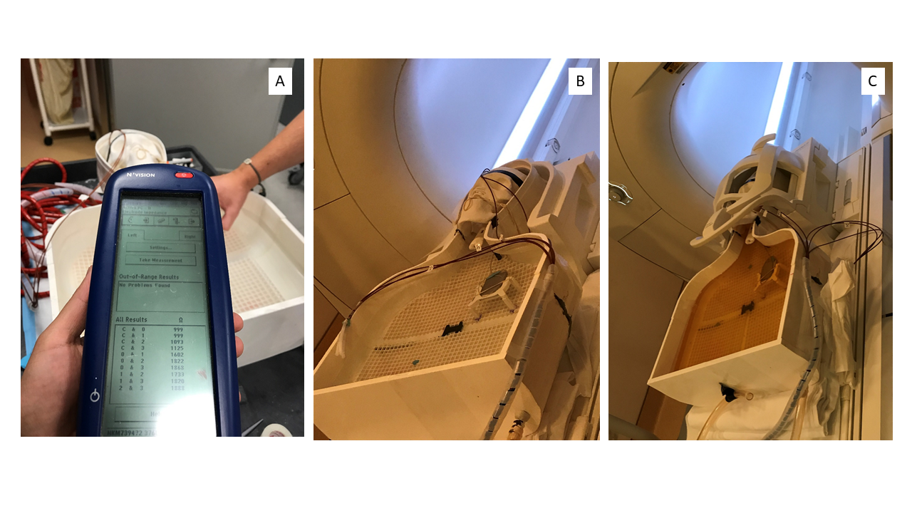
Phantom design and construction: An anthropomorphic phantom was designed and constructed based on CT images of a patient with a deep brain stimulation implant. Images were segmented using thresholding, smoothing and Island removal functions in 3D slicer (3D Slicer 4.10). The segmented silhouette of the patient was used to design phantom’s outer shell which was then caudally extruded and capped at the abdominal end using Rhino 3D CAD tool (Rhino 6.0). The skull was splitted into two halves connecting at a coronal plane allowing the skull to be reopened and refilled with different brain-mimicking tissue material. Phantom parts were 3D printed in ABS plastic and coated with acrylic for waterproofing (Figure 1). We also designed and 3D printed grids and stands that allowed DBS implanted pulse generator (IPG) and extension cables to be precisely positioned at locations analogous to clinical practice.DBS device configurations: A Medtronic DBS system consisting of the lead (model 3387), extension (model 3708660), and IPG (Activa PC-37601) was positioned inside the phantom following eight clinically relevant configurations. Two flouroptic temperature probes were attached to contacts 0 (most distal contact) and 2 of the lead and inserted into the skull at the entry point and penetration angle analogous to clinical approach to reach right subhtalamic nucleus. The skull was filled with agar gel doped with NaCl with the conductivity and relative permittivity measured with a network analyzer to be 0.40 S/m and 78. The IPG was positioned at the location of left pectoral muscle, mimicking contralateral DBS configuration (Figure 2). The extra cranial medium was either filled with saline alone, with conductivity matched to muscle (0.50 S/m), or saline topped with a thin layer of oil (σ = 0 S/m, εr = 3) to cover the upper face of the IPG. The latter happens in obese patients who have more subcutaneous fat. For each scenario, DBS lead and extension were routed along one of typical trajectories illustrated in Figure 3.
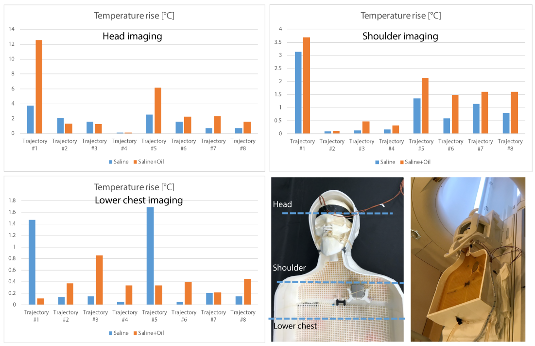
RF exposure: Imaging was performed in a Siemens Aera 1.5T MRI scanner using a T1-TSE sequence (TR=814 ms, TE=7.3 ms, B1 rms= 4.1 µT). For each body composition and DBS configuration, we measured temperature rise during 4 minutes of RF exposure for the phantom located at three different imaging landmarks corresponding to head, shoulder and lower chest imaging.
Results
A total of 48 measurements were performed. The Measured temperature increase at the most distal contact (contact-0) has been presented in the plots (Figure 5). The temperature increase recorded by probe connected to the contact-2 were close to the values at contact-0 (within 10%). RF heating was maximum for the phantom positioned at head landmark (2.56±3.03 °C), followed by shoulder landmark (1.18±1.08°C) and lower chest landmark (0.44±0.49°C). Addition of subcutaneous fat significantly increased RF heating (>3-fold) for lead trajectories where no extracranial loop was present and the excess length of extension was instead looped around the IPG. Introduction of concentric loops simultaneously at the surgical burr hole and on the temporal bone reduced RF heating by 55% on average over all body compositions and imaging landmarks. The effect was extreme in the case of a no-loop trajectory in a patient with subcutaneous fat (0.1°C vs 12°C).Discussions and Conclusions
The absence of obvious adverse effects in patients with electronic implants who have undergone off-label MRI have resulted in a more lenient approach toward MRI RF safety based on limited data. This, can jeopardize patient’s safety, as it only takes one unfortunate combination of factors to cause irreversible thermal damage. We show that variations in DBS device configuration and patient’s body composition introduces extreme fluctuations in RF heating. These results strongly suggest that benefits of off-label MRI in patients with conductive implants be evaluated against realistic risks in consideration of patients’ biological factors and possible device configurations. We are now in the process of evaluating these effects during MRI at 3T and in multi-compartment phantoms with shapes and range of tissue conductivities representing different body types.Acknowledgements
This work has been supported by NIH grants R00EB021320, R03EB025344, and R03EB024705.
References
[1] A. Boutet et al., "Functional MRI safety and artifacts during deep brain stimulation: experience in 102 patients," Radiology, p. 190546, 2019.
[2] I. Hancu et al., "On the (Non‐) equivalency of monopolar and bipolar settings for deep brain stimulation fMRI studies of Parkinson's disease patients," Journal of Magnetic Resonance Imaging, vol. 49, no. 6, 2018.
[3] E. Mattei et al., "Complexity of MRI induced heating on metallic leads: experimental measurements of 374 configurations," Biomedical engineering online, vol. 7, no. 1, p. 11, 2008.
[4] Bhusal B, Bhattacharyya P, Baig T, Jones S, Martens M. Measurements and simulation of RF heating of implanted stereo electroencephalography electrodes during MR scans. Magn Reson Med. 2018; 80: 1676– 1685.
[5] C. McElcheran et al., "Numerical Simulations of Realistic Lead Trajectories and an Experimental Verification Support the Efficacy of Parallel Radiofrequency Transmission to Reduce Heating of Deep Brain Stimulation Implants during MRI," Nature Scientific Reports vol. 9, no. 1, p. 2124, 2019.
[6] E. Kazemivalipour et al., "Reconfigurable MRI technology for low-SAR imaging of deep brain stimulation at 3T: Application in bilateral leads, fully-implanted systems, and surgically modified lead trajectories," Neuroimage, vol. 199, pp. 18-22, 2019.
[7] L. Golestanirad et al., "Changes in the specific absorption rate (SAR) of radiofrequency energy in patients with retained cardiac leads during MRI at 1.5 T and 3T," Magnetic resonance in medicine, vol. 81, no. 1, pp. 653-669, 2019.
[8] L. Golestanirad et al., "RF heating of deep brain stimulation implants in open-bore vertical MRI systems " Magnetic resonance imaging, vol. InPress, 2019.
[9] L. Golestanirad et al., "RF-induced heating in tissue near bilateral DBS implants during MRI at 1.5 T and 3T: The role of surgical lead management," NeuroImage, vol. 184, pp. 566-576, 2019.
[10] L. Golestanirad, B. Keil, J. Kirsch, J. Pilitsis, and L. L. Wald, "Reconfigurable coil technology can substantially reduce RF heating of bilateral deep brain simulation leads during MRI at 1.5 T: First in-vitro studies with realistic implant trajectories," in International Society of Magntic Resonance in Medicine, 2019.
[11] P.-S. Wei, B. Yang, C. McElcheran, L. Golestanirad, and S. J. Graham, "Reducing Radiofrequency-induced Heating in Realistic Deep Brain Stimulation Lead Trajectories using Parallel Transmission," Proc. Int. Soc. Magn. Reson. Med., vol. 26, 2018.
[12] C. E. McElcheran, B. Yang, K. J. Anderson, L. Golestanirad, and S. J. Graham, "Parallel radiofrequency transmission at 3 tesla to improve safety in bilateral implanted wires in a heterogeneous model," Magnetic resonance in medicine, vol. 78, no. 6, pp. 2406-2415, 2017.
[13] C. McElcheran et al., "Parallel Transmission for Heating Reduction in Realistic Deep Brain Stimulation Lead Trajectories," Proc. Intl. Soc. Mag. Reson. Med. , vol. 25, 2017.
[14] C. McElcheran, L. Golestanirad, and S. Graham, "Heating Reduction in Unilateral And Bilateral Implanted Leads At 3T Using Parallel Radiofrequency Transmission in a Heterogeneous Head Model," Proc. Intl. Soc. Mag. Reson. Med., vol. 24, 2016.
[15] L. Golestanirad, L. M. Angelone, M. I. Iacono, H. Katnani, L. L. Wald, and G. Bonmassar, "Local SAR near deep brain stimulation (DBS) electrodes at 64 MHz and 127 MHz: A simulation study of the effect of extracranial loops " Magnetic Resonance in Medicine vol. 88, no. 4, pp. 1558-1565, 2016.
[16] C McElcheran, L. Golestanirad, and S. Graham, "Reduced Heating of Implanted Electrical Conductors Using Parallel Radiofrequency Transmission," Proc. Intl. Soc. Mag. Reson. Med. 22 2014.
[17] K. Fujimoto, L. M. Angelone, E. Lucano, S. S. Rajan, and M. I. Iacono, "Radio-Frequency Safety Assessment of Stents in Blood Vessels During Magnetic Resonance Imaging," Frontiers in Physiology, vol. 9, 2018.
[18] L. Golestanirad et al., "Variation of RF heating around deep brain stimulation leads during 3.0 T MRI in fourteen patient-derived realistic lead models: The role of extracranial lead management," Proc. Intl. Soc. Mag. Reson. Med. 25 2017.
[19] K. B. Baker, J. Tkach, J. D. Hall, J. A. Nyenhuis, F. G. Shellock, and A. R. Rezai, "Reduction of magnetic resonance imaging-related heating in deep brain stimulation leads using a lead management device," Neurosurgery, vol. 57, no. 4, pp. 392-397, 2005.
Figures