4171
1.5T and 3T MRI safety of a deep brain stimulation system: in vitro temperature measurements1Lysholm Department of Neuroradiology, UCLH, London, United Kingdom, 2UCL Institute of Neurology, :ondon, United Kingdom, 3Department of Clinical and Experimental Epilepsy, UCL Institute of Neurology, :ondon, United Kingdom, 4Administration of Medical Physics, King Abdullah Medical City (KAMC), Makkah, Saudi Arabia, 5Unit of Functional Neurosurgery, Sobell Department of Motor Neuroscience and Movement Disorders, UCL Institute of Neurology, London, United Kingdom
Synopsis
The aim of this study was to compare RF-induced heating in an in vitro model of an implanted Boston Scientific Gevia DBS device between 1.5T and 3T MRI. We assessed temperature changes in a phantom simulating a patient with a bilateral DBS neuromodulation device in different transmit coils, lead configurations and 3T B1 shimming options. Highest temperature increase was recorded at the distal electrode contact during 1.5T MRI in the body transmit coil. Phantom tests showed that lead arrangement, B1 shimming and DBS system configuration can have significant effect on temperature recorded near the contacts.
Introduction
More than 150,000 patients have been implanted worldwide with deep brain stimulation (DBS) devices1, an established treatment for managing movement disorders, such as Parkinson’s disease (PD), dystonia and essential tremor. In our centre, post-operative MRI is essential to the implantation workflow, used to verify electrode locations and confirm there are no post-operative complications2. Moreover, MRI may be indicated for routine clinical purposes during the patients’ lifetime post DBS implantation. RF-induced heating in the tissue surrounding the implants is the main concern when scanning patients with DBS systems. A device has been recently introduced (Boston Scientific Gevia DBS system) offering increased battery longevity with a more complex electrode structure (Vercise directional leads) allowing greater control of the shape, position and direction of neurostimulation. The system’s MRI labelling restricts scanning to 1.5T, under strict B1+rms limits. Whilst there have been publications assessing the safety of DBS systems in vitro and with numerical simulations 2-6, we are not aware of any reports assessing this specific system. The aim of this study was to compare RF-induced heating in an in vitro model of an implanted Boston Scientific Gevia DBS device between 1.5T and 3T MRI.Methods
A DBS system of a Boston Scientific Gevia implantable pulse generator (IPG) connected to two Vercise electrode leads was placed inside a torso phantom containing a polyacrylic acid mixture, as described previously3. Temperatures were recorded using a fibre optic thermometer (Neoptix, Canada) with probes placed at the left (L1) and right (R1) distal DBS electrode contacts, and at directional contacts (Rd, Ld). Measurements were performed on 1.5T (Avanto, Siemens) and 3T (Prisma, Siemens) using body transmit and head transmit-receive coils. Low and high RF exposure Turbo Spin Echo (TSE) sequences were used; the scanner-reported head, whole body SAR and B1+rms values recorded. Temperature changes (ΔT) were calculated by subtraction of a baseline value (averaged temperature for 10s prior to MRI sequence) for each time-point during the 6 mins scan. We assessed the effect of placing leads in various configurations, and of using different B1 shimming options (circular polarised (CP), elliptical mode and low SAR) on ΔT (at 3T only). In addition, temperature changes were recorded for a leads-only configuration.Results
At 1.5T, for the lower-RF exposure TSE sequence (Boston Scientific B1+rms limits of 1.2 μT for the body coil transmit and 2.0 μT for the transmit-receive head coil) and a lead/DBS IPG configuration resembling that of our clinical practice, ΔT did not exceed the current guideline limits of 1°C7. During higher-RF exposure TSE sequences the maximum ΔT were 9.6°C using the body transmit coil at 1.5T (at the tip of the right electrode; scanner-reported head SAR 2.8W/Kg, B1+rms 4.1μT) and 2.1°C using the body transmit coil at 3T (at the tip of both electrodes; scanner reported head SAR 2.6W/Kg, B1+rms 2.8μT). Example results using the body transmit coil are shown in figure 1. Varying the right lead arrangement resulted in variations in ΔT in the range of 1.2-4.8°C at the right tip, and 3.1-7.8°C at the right directional contact. The CP B1 shimming mode led to elevated ΔT at all contacts compared to the elliptical mode. When scanning leads only using the body transmit coil ΔT remained below 1°C for both 1.5T and 3T.Discussion/Conclusion
Consistent with the manufacturer’s stated labelling conditions, ΔT did not exceed 1°C guideline limits at 1.5T for the lower RF exposure TSE sequence. Phantom tests showed that lead arrangement, B1 shimming and DBS system configuration can have significant effect on temperature recorded near the contacts. Whilst reassuring, the results of this study illustrate the complexity of RF-induced heating effects in the vicinity of DBS leads. Further tests and numerical simulations are required to fully assess the risks at 3T and higher field strengths.Acknowledgements
No acknowledgement found.References
1. Zrinzo, L., Yoshida, F., Hariz, M. I., Thornton, J., Foltynie, T., Yousry, T. a, & Limousin, P. Clinical safety of brain magnetic resonance imaging with implanted deep brain stimulation hardware: large case series and review of the literature. World neurosurgery, 2011; 76(1-2), 164–72.
2. Kahan, J., Papadaki, A., White, M., Mancini, L., Yousry, T, Zrinzo, L., et al. The Safety of Using Body-Transmit MRI in Patients with Implanted Deep Brain Stimulation Devices. PLoS ONE 2015; 10(6): e0129077.
3. Carmichael, D. W., Pinto, S., Limousin-Dowsey, P., Thobois, S., Allen, P. J., Lemieux, L., Yousry, T., Thornton, J. S. Functional MRI with active, fully implanted, deep brain stimulation systems: safety and experimental confounds. NeuroImage 2007; 37(2), 508–17. 4. Sammartino F., Krishna V., Sankar T., Fisico J., Kalia S.K., Hodaie M., Kucharczyk W., Mikulis D.J., Crawley A., Lozano A.M.3-Tesla MRI in patients with fully implanted deep brain stimulation devices: a preliminary study in 10 patients J Neurosurg 2017; 127:892–898
5. Golestanirad L., Kirsch J., Bonmassar G., Downs S., Elahi B., Martin A., Iacono M.I., Angelone L.M., Keil B., Wald L.L., Pilitsis J. RF-induced heating in tissue near bilateral DBS implants during MRI at 1.5 T and 3T: The role of surgical lead management.NeuroImage 2019; 184: 566–576
6. Boutet A., Hancu I., Saha U., Crawley A., Xu D.S. et al. 3-Tesla MRI of deep brain stimulation patients: safety assessment of coils and pulse sequences. J Neurosurgy. 2019; 1-9
7. HPA Protection of Patients and Volunteers Undergoing MRI Procedures: Advice from the Health Protection Agency (RCE-7); 2008.Figures
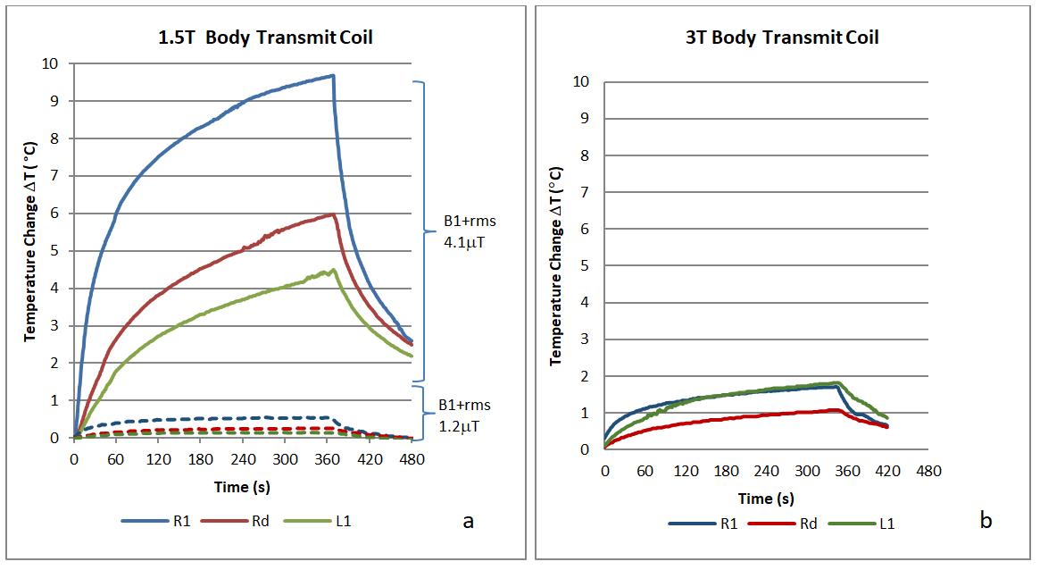
Figure 1. Temperature changes DT during a) high RF exposure TSE sequence at 1.5T (Scanner reported head SAR 2.8W/Kg, B1+rms 4.1μT) and low RF exposure TSE (head SAR 0.2W/Kg, B1+rms 1.2μT) and b) high RF exposure TSE sequence at 3T (head SAR 2.6W/Kg, B1+rms 2.8μT) (R1 = right tip, L1 = left tip, and Rd = right directional contact)