4169
A simulation study of the SAR10g dependence of a microwave applicator for MR-guided ablation of hepatic tumors at 1.5T1Technical University of Delft, Delft, Netherlands, 2Radiology Department, Leiden University Medical Center, Leiden, Netherlands
Synopsis
Magnetic resonance (MR) guidance of microwave ablation of hepatic tumors could help to overcome poor visualisation of the ablation zone by ultrasound, may allow better intraprocedural confirmation of technical success. The ablation applicator is a metallic rod and can potentially act as an ‘antenna’ during MR imaging which can produce unwanted localized heating in nearby tissue. In this abstract, we investigated via electromagnetic simulations the maximum SAR10g changes caused by applicators of different radius and length and for various insertion angles.
Introduction
Ablations are alternative treatments to surgical removal of hepatic tumors. Microwave ablation (MWA) enables high intra-tumoral temperatures resulting in larger ablation zones, is less susceptible to heat-sink effects in comparison to RF ablation, and is associated with shorter ablation times1-3.Magnetic resonance (MR) guidance of MWA of hepatic tumors could help to overcome the poor visualisation of the ablation zone by ultrasound and may allow better intraprocedural confirmation of technical success4, 5. It could allow precise applicator placement in small lesions via real time imaging, enable free selection of imaging planes and it is not associated with radiation.
During MR imaging, microwave energy is “pulsed” into the body and body absorbs some of the RF power. The Specific Absorption Rate (SAR) is a measure of the rate at which energy is absorbed by the human body when exposed to an electromagnetic field. It is well-known that metallic devices can act as an “antenna” and concentrate this energy, which can lead to excessive local heating. The ablation applicator is a cylindrical metallic rod that can be of different diameters and lengths. In this work, we simulate changes of maximum SAR10g induced by applicators in MRI guided thermal ablation at 1.5T.
Methods
Electromagnetic simulations were performed in CST Microwave Studio 2019 (CST Studio Suite, Computer Simulation Technology, Darmstadt, Germany). To evaluate SAR10g, simulations of a voxel models placed in a 1.5T birdcage body coil have been performed (Figure 1(a)). All results were normalized to 1W of accepted power. MWA applicators were modelled as brass cylinders with radius and lengths that correspond to real applicators shown in Figure 2. All applicator tips were inserted at a depth of 50 mm into the liver.Simulations were performed for ten applicators (Figure 2) while the insertion angle was changed from 0° to +- 60°. For applicators #1 to #6 the angle was varied in the ZY plane (as in Figure 1(b)), while for applicators #7 to 1#0 the angle was changed in the XY plane (as in Figure 1(c)).
To show the dependence of the maximum SAR10g on the body size, three voxel models were simulated - Gustav, Laura and Hugo. For these simulations the insertion angle and applicators’ lengths were varied.
Maximum SAR10g was also calculated for cases with one, three and six applicators (as is commonly used in ablation procedures) in realistic placements within the liver.
Results
Figure 3 (a) shows the dependence of the maximum SAR10g values on the insertion angles for ten applicators and (b) shows mean values of the maximum SAR10g shown in Figure 3 (a). The simulated maximum SAR10g of the voxel model Gustav in 1.5T birdcage coil without an applicator in place was 0.41 W/kg. The highest influence on maximum SAR10g was at an insertion angles of +-15°. The maximum SAR10g value increased around 20% compared to 0.48 W/kg.Figure 4 shows the maximum SAR10g on three different voxel models (Gustav, Laura and Hugo) for variable insertion angles and applicator’s lengths. The calculated maximum SAR10g for voxel models without applicators was 0.41 W/kg for Gustav, 0.19 W/kg for Hugo and 0.1 W/kg for Laura. The maximum SAR10g was almost constant for voxel models Laura and Hugo while the highest variations were observed for voxel model Gustav.
Figure 5 shows simulated maximum SAR10g corresponding to the real ablation cases with one, three and six applicators. The highest calculated maximum SAR10g was 0.64 W/kg for a single applicator which has the highest insertion angle and insertion depth compared to the other two cases. The other two cases showed very similar maximum SAR10g.
Discussion and conclusions
In this simulation study the largest influence on maximum SAR10g was found to be the insertion angle of the ablation applicator. The maximum SAR10g increase of 20% compared to the value obtained without applicator was for an insertion angles of +-15° in ZY plane. In the case of other insertion angles the maximum SAR10g was slightly lower than that without applicators, which can be explained by a slight detuning of the birdcage coil due to the presence of the applicator. In practise this, of course, will result also in a reduction in the transmit efficiency of the body coil, requiring more power for a given tip angle: the effect on transmit efficiency per square root of SAR remains to be investigated.The changes in maximum SAR10g for different body models (and different applicators and insertion angles) were the highest for voxel model Gustav and almost constant for the models Laura and Hugo.
For the case of multiple applicators, the effects confirm that the insertion angle is the most important criterion, and indicate that the SAR changes from the three applicators can effectively be added together.
The appearance of localized heating due to the presence of applicators has not been observed. Future work will include investigation of B1+ field perturbations by the presence of the applicator.
Acknowledgements
this work was made possible by European Research Council Advanced Grant (670629 NOMA MRI).References
Gillams A, Goldberg N, Ahmed M et al. Thermal ablation of colorectal liver metastases: a position paper by an international panel of ablation experts, the interventional oncology sans frontieres meeting 2013. Eur Radiol. 2015;25:3438– 3454.
Laeseke PF, Lee FT, Sampson LA, van der Weide DW, Brace CL. Microwave ablation versus radiofrequency ablation in the kidney: high-power triaxial antennas create larger ablation zones than similarly sized internally cooled electrodes. J Vasc Interv Radiol. 2009;20:1224–1229.
Alexander ES, Wolf FJ, Machan JT et al. Microwave ablation of focal hepatic malignancies regardless of size: a 9-year retrospective study of 64 patients. Eur J Radiol. 2015;84:1083–1090.
Hoffmann R, Rempp H, Kesler DE, Weis J, Pereira PL, Nikolaou K, Clasen S. MR-guided microwave ablation in hepatic tumours: initial results in clinical routine. Eur Radiol. 2017; 27:1467–1476.
Hoffmann R, Kessler DE, Weiss J, Clasen S, Pereira PL, Nikolaou K, Rempp H. Preclinical evaluation of an MR-compatible microwave ablation system and comparison with a standard microwave ablation system in an ex vivo bovine liver model. Int J Hyperthermia. 2017;33(6), 617-623.
Figures
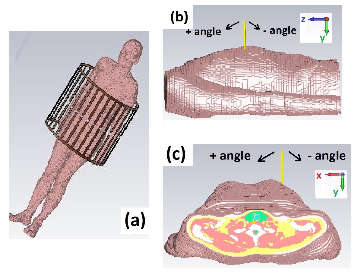
Figure 1. (a) Simulated setup – voxel model inside of 1.5T birdcage coil. (b) Insertion angle of the applicators - ZY plane and (c) insertion angle of the applicator - XY plane.
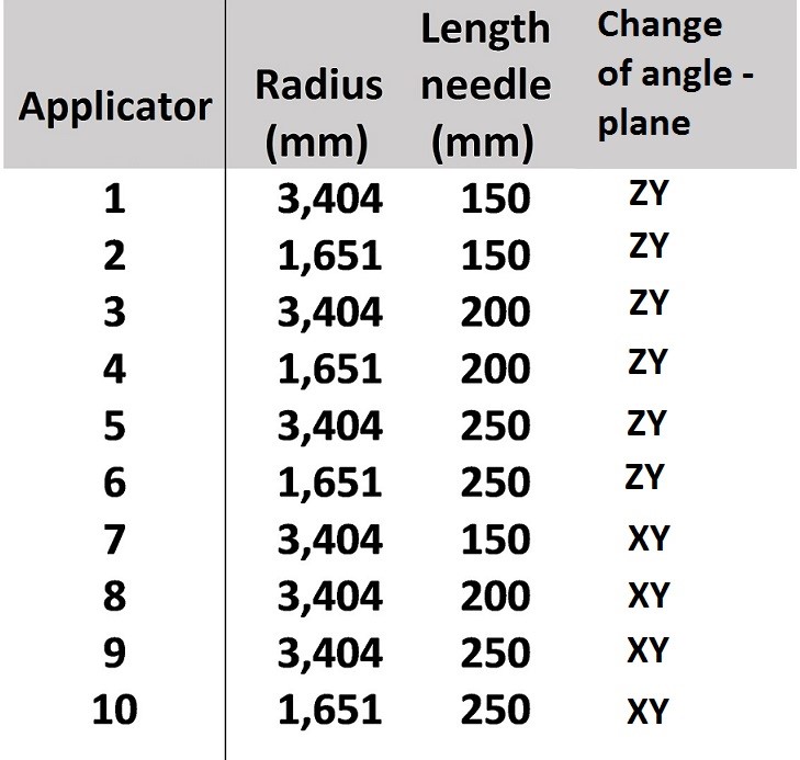
Figure 2. List of parameters for ten different applicator’s radius-length combinations used in SAR simulations.
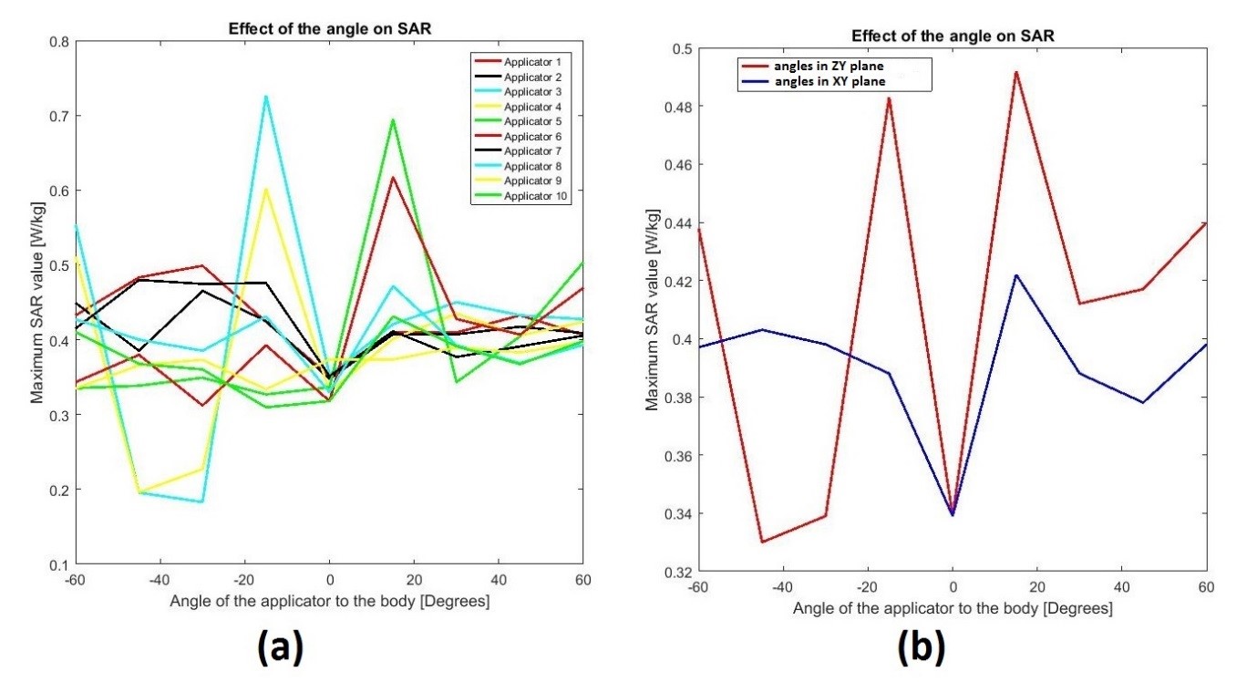
Figure 3. (a) Simulated maximum SAR10g values of ten different applicators and various insertion angles. (b) Mean value of maximum SAR10g versus insertion angle of the applicator.
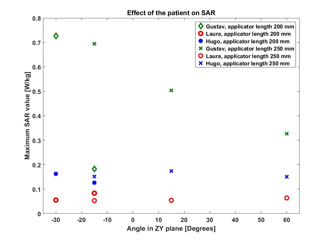
Figure 4. Simulated maximum SAR10g on three different voxel models, Gustav, Laura and Hugo for variable applicator insertion angles and variable applicator’s lengths.
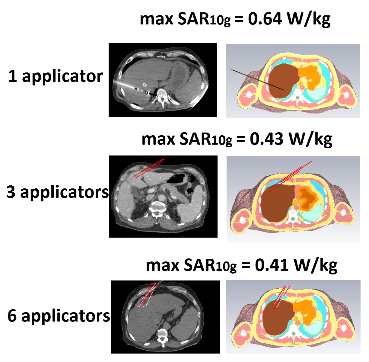
Figure 5. Simulated maximum SAR10g for ‘’real’’ cases of ablation applicator positions for a cases of one, three and six applicators.