4165
Approach to reduce the measurement volume to determine spatial distribution of power deposition around a straight lead according to ISO/TS 109741MR:comp GmbH, Testing Services for MR Safety & Compatibility, Gelsenkirchen, Germany, 2TU Dortmund University, Dortmund, Germany, 3MRI-STaR - Magnetic Resonance Institute for Safety, Technology and Research GmbH, Gelsenkirchen, Germany
Synopsis
To determine the RF-induced heating of an active implant, it is necessary to measure the 3D distribution of the power deposition in the hotspot volume. By measuring the Erms distribution around a test object, different influences on the decay were investigated. It was shows that radial decay can be described with a single model along test object. This model is normalized to a defined distance. The measurement values along the TO at this distance, can be used to scale the model and the power deposition inside the hotspot volume can be calculated. This leads to an advantage in time saving.
Introduction
RF-induced heating is one of the safety issues for active implantable medical devices (AIMDs) in MRI. ISO/TS 10974 [1] describes different ways to determine the spatial power deposition for hotspots around an AIMD. One approach is a 3D measurement of temperature or SAR distribution. After showing the validity of radial symmetry [2] and the influence of probe positioning for reproducibility [3], this study examines the possibility of reducing the 3D measurement to a small measurement volume followed by numerical reconstruction of the whole volume.Methods
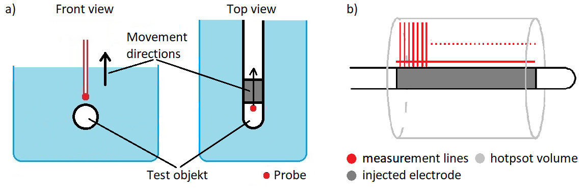
The test object (TO), a straight multi-electrode lead, is placed in a phantom in saline solution. Spatial power distribution was measured with an Erms-probe (SAR Probe, EX3DV4, SPEAG) placed above TO and moved along and in radial direction to the lead (Fig. 1a). The calculation of the power deposition in a hotspot volume is defined in [1].Two electrodes were injected with 64 MHz. For each position along the lead, the distribution in radial distance was measured. Radial distance was increased in 0.2 mm steps up to 10 mm and in 0.1 mm steps along the lead for each measurement (Fig. 1b). Thus, a 2D plane of the distribution above the electrode was measured, which is used as reference.
Different combinations of two injected electrodes and injected power ratios were used to evaluate the influence on the radial decay. Every value along the radial line was normalized to its own maximum at smallest distance to the TO.
For a more precise modelling of radial decay, a temperature probe (TS5, Optocon) was used to measure three points in close proximity to the TO, which the Erms-probe cannot reach. The temperature probe was placed in the middle of the injected electrode. Temperature gradient was measured over 10 seconds and converted in corresponding Erms value. Radial distance for the Erms-probe was increased up to 30 mm to enhance the number of data points for the fitting algorithm.
To prove that the model is also valid in a MR setup the TO is placed in a RF-coil (1.5 T MITS, SPEAG). The Erms-probe was moved along the TO at a defined distance. For the measurement in radial direction the probe was placed as close as possible to the electrode at the maximum value from the measurement along TO. Radial distance was increased up to 10 mm from this point. This measurement is done with and without TO in place, to subtract the background field.
To compare the 2D measurement with the radial model function, the volume integral for both cases was calculated using radial symmetry. For the 2D measurement for each radial line, the corresponding circular disk is calculated and added up to a cylindrical volume.
For calculating the power deposition with the model function, the model function is multiplied by each of the values along the TO. With this, the circular disks are calculated and finally the power deposition. The hotspot volume is defined as a location with greater SAR than 25% of the highest value along TO [1].
Results
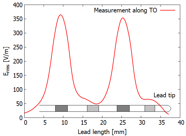
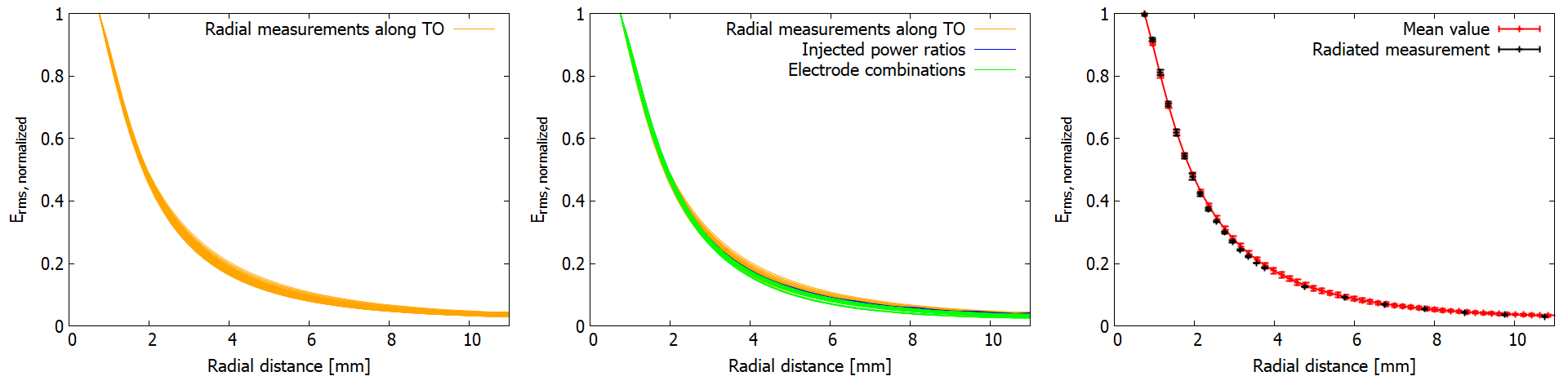
Figure 2 shows the values along the TO for the injected case. The location of the electrodes can be clearly identified. These values are used to scale the normalized model to every position along TO.Figure 3a shows the radial decay along two electrodes, normalized to the maximum value at closest distance to the TO. In figure 3b the radial decay for different combinations of injected electrodes and different injected power rations were added. The values from the measurement inside the RF-coil and mean values and standard deviation from Fig. 3b are shown in Fig. 3c.
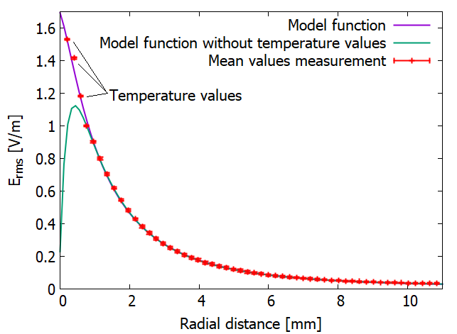
The model function is shown in Figure 4 and was obtained from the mean values from the measurement and the temperature values. Without the temperature values, the model underestimates the distribution drastically.
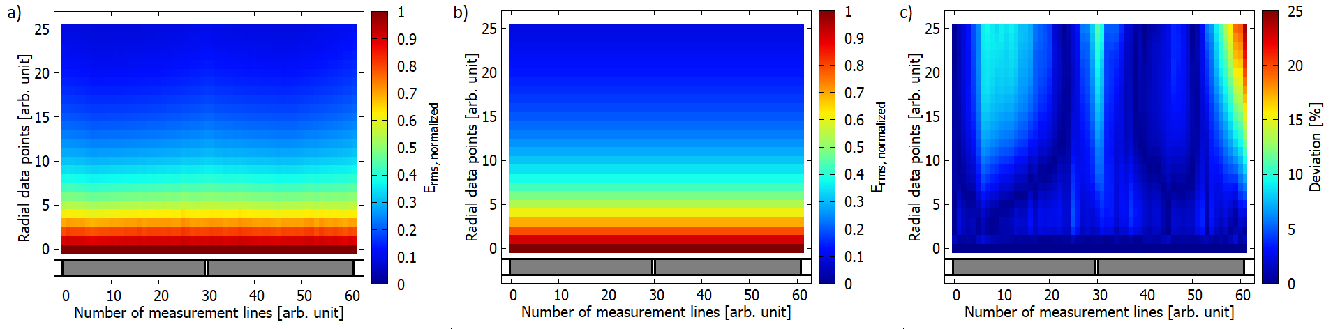
Figure 5 shows the measured 2D Erms distribution along the TO (yellow lines Fig. 1a), the reconstructed plane with the model and the deviation. The average deviation over the plane is 3.4 %.
Discussion
The results in Fig. 3 show, that there is no significant difference for the radial decay along the electrode. Furthermore, there is no influence of different combination of injected electrodes or different injected power ratios.The results from the measurement in the RF-coil show, that the model is also valid for the radiated case. Therefore, the model function can be obtained in the injection setup with one injected electrode and the profile along the TO from the radiation setup. From these two lines the whole distribution of hotspot volume can be reconstructed. The power deposition calculated from the measured data in Fig. 5a is $$$P=182.7$$$ W and for reconstructed data from Fig. 5b the power is $$$P=173.32$$$ W for two injected electrodes.
Conclusion
This study shows that the decay can be described with a single model over the whole length of the hotspot along the TO. This model is normalized to a defined distance. With a measurement along the TO at this distance, the power deposition inside the hotspot volume can be calculated. This approach is very time-saving compared to the full 3D measurement without a significant increase in uncertainty.Acknowledgements
Supported by: Federal Ministry for Economic Affairs and Energy on the basis of a decision by the German Bundestag, grant # ZF4205704BA8.References
[1] Technical specification ISO/TS 10974 “Assessment of the safety of magnetic resonance imaging for patients with an active implantable medical device”; www.iso.org.
[2] F. Ketelsen, J. Kreutner, K. Kröninger, et al. Validity of radial symmetric hotspot distribution around a lead for comparison of different probe types at various orientations to a lead. ISMRM Workshop on MR Safety 2019, Utrecht.
[3] F. Ketelsen, S. Scholz, W.Görtz, et al. The influence of probes positioning for measuring RF-induced 3D-power deposition on a lead with E-field and temperature probes. ESMRMB 2019, 36th Annual Scientific Meeting, Rotterdam.
Figures