4161
Electrodynamics and RF Applicator Concept forSub-nanosecond Pulsed Thermal Magnetic Resonance
1B.U.F.F., Berlin Ultrahigh Field Facility, Max-Delbrück Center for Molecular Medicine in the Helmholtz Association, Berlin, Germany, 2MRI.TOOLS GmbH, Berlin, Germany
Synopsis
This work presents electrodynamic considerations and an RF applicator concept that permit MR imaging and RF energy focusing inside of the human brain using sub-nanosecond broadband electromagnetic pulses. Such pulses can deposit RF energy in a small, focal area for thermal intervention. To meet this goal proof-of-principle is provided through EMF simulations using a dual-mode RF applicator that combines antipodal Vivaldi antennae with loop elements.
Introduction
Temperature is a physical parameter that has a decisive influence on biological processes and its measurement and control are very relevant in clinical practice. UHF-MR employs higher radio frequencies (RF) than conventional MR and has a unique potential to provide imaging with superb spatial resolution, temperature monitoring using MR thermometry and controlled temperature manipulation, denominated as Thermal Magnetic Resonance (ThermalMR). The main challenge to unite MRI with RF induced thermal interventions is the compatibility and integration of RF antennae into a single device. One of the solutions is employed RF applicators comprising broadband antennae, that support operating frequencies customized for imaging and RF heating1. With this multi-element setup, it is common to apply a single RF frequency to generate focal heating using phase and amplitude optimization for the RF applicator to control size, uniformity, and location of the RF energy deposition in the target region with the focal point quality being governed by the radiation pattern of the single RF transmit element, the RF channel count and the thermal intervention radiofrequency of the RF applicator. The use of sub-nanosecond broadband RF pulses2 provides a valuable alternative for thermal intervention, which has spurred the development of antennae for RF pulse radiation cancer treatment3,4. Focusing of sub-nanosecond RF pulses enhances the focal point quality and simplifies calculations for hot spot position planning. Recognizing these opportunities this work presents a dual-mode head RF applicator that permits MRI at 7.0 T and sub-nanosecond pulsed RF heating.Methods
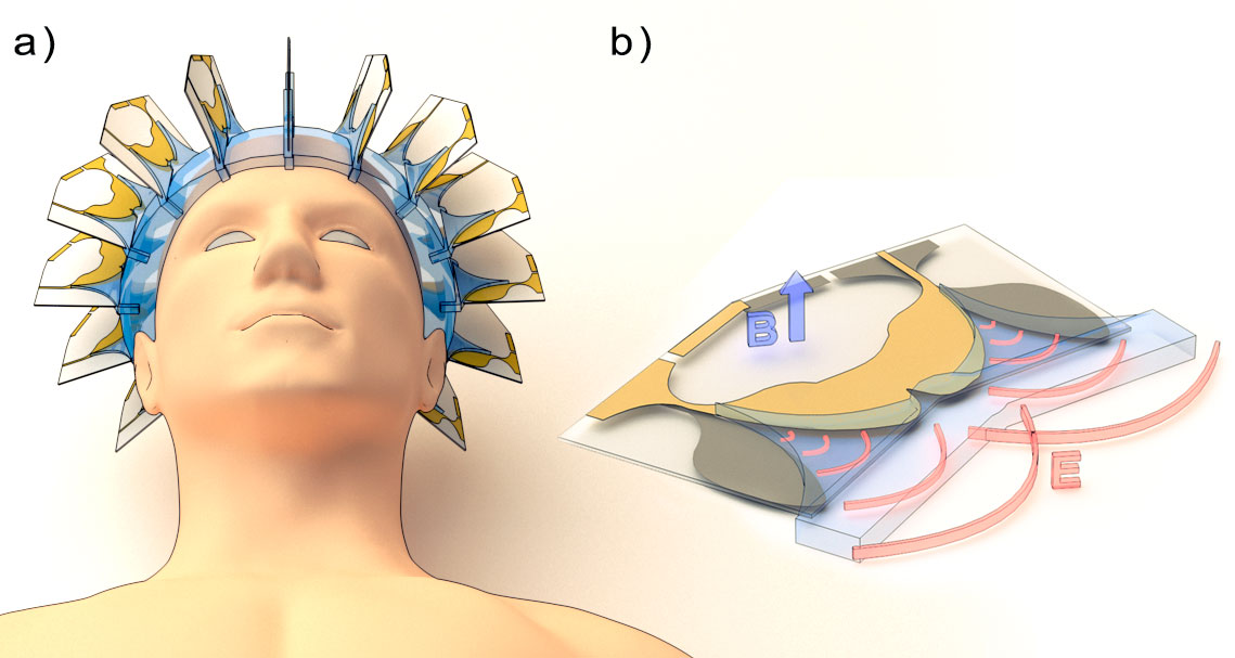
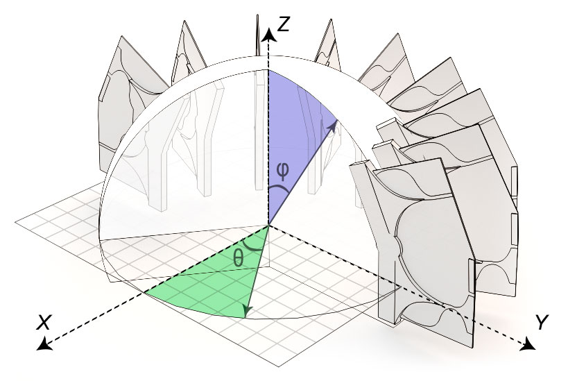
The RF array consists of 16 elements surrounding a spherical water bolus (εr=78.4, σ=5.5e-6 S/m) which conforms to an average head (Figure 1). Each element is a combination of two broadband antipodal Vivaldi antennae, previously proposed for use in thermotherapy5,6. Additional conductors between antenna lobes were used to form a magnetic loop, tuned to the 1H frequency at 7T (297.3 MHz). All 16 loops are the imaging channels, supporting TIAMO technology to compensate transmission field distortions7. In the disclosure of the Vivaldi antennae, water in the form of an exponential shape is integrated for better electromagnetic matching with the bolus material. Every Vivaldi antenna has its fixed coordinates in the spherical coordinate system, where it`s position is determined by the distance from the origin r and two angles θ and φ (Figure 2). This information is necessary for predicting the location of the RF pulse in space after it started to propagate out of the antenna. The pulse wavefront’s collision point governs the position and geometry of the RF heating area and can be controlled via time shift between all antennae, which is in analogy with the phase shift in the conventional approach. Electromagnetic simulations were performed in CST Microwave Studio’s (CST Studio Suite 2018, CST – Computer Simulation Technology GmbH, Darmstadt, Germany) for imaging and RF pulse mode. The imaging mode was simulated with a frequency-domain solver and a uniform head model (εr=60.1, σ=0.61 S/m) placed inside the bolus. Resulting B1+ fields was normalized to 1W of the accepted power. The pulse mode was simulated with the time domain solver and the male voxel model Duke8 for the SAR estimation. A triangle pulse (duration=0.5ns, a rise/fall time=0.25ns) was employed as a reference signal.Results
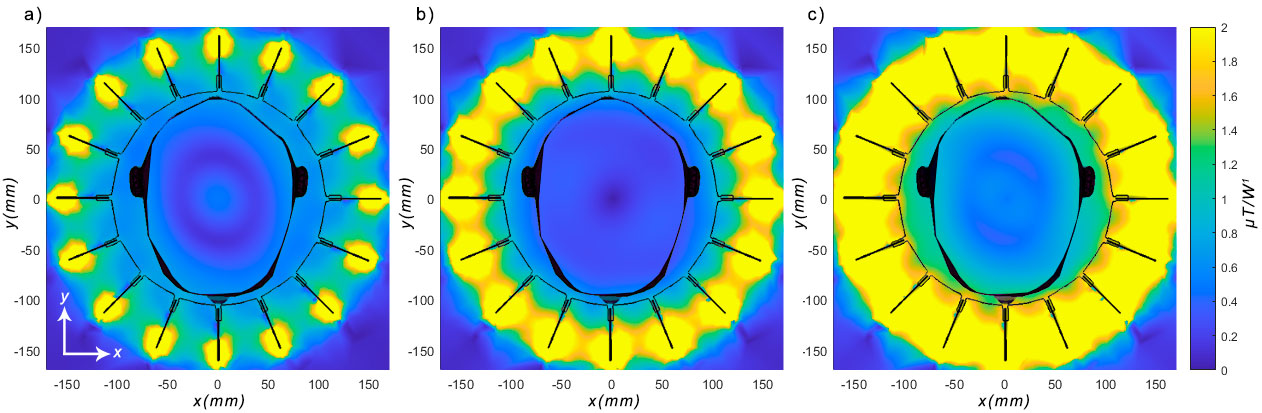
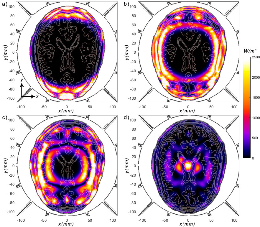
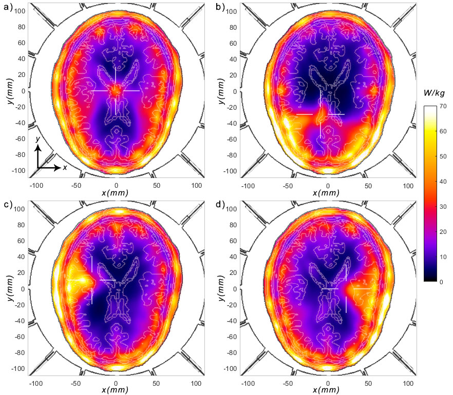
EMF simulations using two-phase sets for the imaging mode show good B1+ coverage of the brain when using the TIAMO approach (Figure 3). For the sub-nanosecond pulse mode, propagation of the RF pulses through the brain can be observed at different time moments by calculating losses in tissues (Figure 4). Our results demonstrate that the array of Vivaldi antennae creates a quasi-circle wavefront with the center at the focus point. The size of the heated region around the focus point depends on the profile of the RF pulses and its width. The use of a triangular pulse is suitable for evaluating the performance of the positioning algorithms. Four different positions of the focal point within the central XY-plane of the brain of the human voxel model Duke were simulated with corresponding time-shifts between each RF antenna. SAR distributions demonstrate the deliberate steering of the SAR hot spot to an arbitrary and more peripheral position (Figure 5). Since the calculations were carried out on healthy tissues, which, compared with the damaged tissue, do not differ significantly in electrical conductivity, there is a significant surface SAR taking place. Increasing the number of pulse channels as well as taking perfusion into account in the EMF simulations can reduce this effect.Discussion and Conclusion
This work demonstrates the concept of a hybrid RF applicator that permits MRI and thermal intervention using sub-nanosecond broadband RF pulses in a single device. The ability to control the position of the heating zone by changing the time-shifts between RF pulse channels was shown. An underestimated hot point position was observed for peripheral regions of the head. This phenomenon can be compensated by adding non-linear properties to the time-shift calculating algorithm. The proposed RF applicator is conceptually appealing to pursue Thermal MR including its application for adjunct tumor therapy or controlled release of therapeutics from thermoresponsive nano-carriers.Acknowledgements
This project has received funding from the European Research Council (ERC) under the European Union's Horizon 2020 research and innovation program under grant agreement No 743077 (ThermalMR).References
1. Winter, L., Özerdem, C., Hoffmann, W., Santoro, D., Müller, A., Waiczies, H., et al. (2013). Design and Evaluation of a Hybrid Radiofrequency Applicator for Magnetic Resonance Imaging and RF Induced Hyperthermia: Electromagnetic Field Simulations up to 14.0 Tesla and Proof-of-Concept at 7.0 Tesla. PloS one 64(2), p. e61661.
2. Schoenbach, K. H., Xiao, S., Joshi, R. P., Camp, J., Heeren, T., Kolb, J. F., et al. (2008). The Effect of Intense Subnanosecond Electrical Pulses on Biological Cells. IEEE Transactions on Plasma Science 36(2), p. 414-422.
3. Li, C., Zhao, Y., Du, J., Zhang, Y., Mi, Y., & Yao, C., et al. (2018). Simulation Study of an Impulse Radiation Antenna Array. IEEE Transactions on Plasma Science 64(2), p. 1-7.
4. Xiao, S., Altunc, S., Kumar, P., Baum, C. E., & Schoenbach, K. H. (2010). A Reflector Antenna for Focusing Subnanosecond Pulses in the Near Field. IEEE Antennas and Wireless Propagation Letters 64(2), p. 12-15.
5. Aldhaeebi, M. & Elshafiey, I. (2014). New Antenna Design for Hyperthermia Treatment of Human Head. Proceedings - UKSim-AMSS 16th International Conference on Computer Modelling and Simulation, UKSim 2014 64(2), p. 96-100.
6. Merunka, I., Fiser, O., Vojackova, L., Vrba, J., & Vrba, D. (2014). Array of balanced antipodal Vivaldi antennas used for microwave hypertermia treatment of neck cancer. In 2014 24th International Conference Radioelektronika (pp. 1-4). IEEE.
7. Orzada, S., Maderwald, S., Poser, B., Bitz, A., Quick, H., & Ladd, M., et al. (2010). RF excitation using Time Interleaved Acquisition of Modes (TIAMO) to address B1 inhomogeneity in high-field MRI. Magnetic resonance in medicine: official journal of the Society of Magnetic Resonance in Medicine / Society of Magnetic Resonance in Medicine 64(2), p. 327-33.
8. Christ A, et al. The Virtual Family - Development of surface-based anatomical models of two adults and two children for dosimetric simulations. Phys Med Biol. 2010;55(2).
Figures