4140
Investigation of the impact of RF heating on the treatment temperature during MRI-guided cryoablation at 1.5T
Aiming Lu1, David A Woodrum1, Christopher P Favazza1, Joel P Felmlee1, Brian T Welch1, Jacinta Browne1, and Krzysztof R Gorny1
1Radiology, Mayo Clinic, Rochester, MN, United States
1Radiology, Mayo Clinic, Rochester, MN, United States
Synopsis
MRI-guided cryoablation is a promising minimal invasive approach to treat localized tumors. Since the cryoneedles used in this system are metallic and the gas lines have metallic components, RF heating could occur during MR imaging. Our phantom study demonstrated temperature increase of more than 100 °C due to a sequence with moderate SAR of 2.1W/kg.In this work, we demonstrate that RF heating caused by the real-time monitoring MRI sequence could potentially affect the temperature course near the cryoneedles and therefore affect the treatment efficacy, especially when angiocath was used to aid the cryoneedle placement.
Introduction
MRI-guided cryoablation is a promising minimally invasive approach to treat localized tumors. There is a MRI-conditional cryoablation system that is commercially available and widely used clinically. Since the cryoneedles used in this system constitute a potential RF heating risk during MRI as these needles are made from metallic non-magnetic nickel-chromium-based superalloy (Iconel) and the connected high pressurized gas lines have a metallic component (70/30 Cu/Ni). Although no incidents of RF burns have been reported in literature to the best of our knowledge, a patient recently suffered a skin burn during a MRI-guided liver treatment our institution. In our follow-up phantom investigation, consistent RF heating during imaging was observed. Although the degree of temperature increase was highly dependent on a variety of factors, temperature increases of more than 100 °C occurred using a sequence with moderate SAR—2.1W/kg. Not only did tis result raised safety concerns regarding MRI-guided cryoablation, but it also raised concerns regarding the impact of RF heating on treatment efficacy.. In this work, we demonstrate that RF heating caused by a standard real-time monitoring sequence could potentially affect the temperature evolution near the cryoneedle tip and therefore, affect the treatment efficacy. Furthermore, this impact was compounded while a catheter needle (AgiocathTM) was used to aid cryoneedle placement.Materials and methods
Experiments were performed on a 1.5T scanner (Ingenia, Philips Healthcare, Best, Netherlands) using the Visual-ICE MRI system (Galil Medical, Yokneam, Israel) on porcine tissue phantoms. An IceRod MRI 1.5 straight cryoneedle (17.5cm shaft length, 17 Gauge) was inserted ~10cm into the phantom both with and without a 14G Angiocath. When the Angiocath was used, it was inserted into the phantom first, the needle was removed, and the IceRod was then advanced inside Angiocath sheath into the phantom. The gas line was connected to the mobile connection panel (MCP), which was in turn connected to the Visual-ICE system. Four fiber optic temperature sensors (Neoptix, Qualitrol, Fairport, NY) were attached along the shaft of the cryoneedle at different locations: tip of the IceRod, tip of the Angiocath (~2cm from the tip of the IceRod), 5cm from the tip of the IceRod and at the surface of the phantom (~10cm from the IceRod tip). The experiment setup is shown in Figure 1. A proton density-weighted (PD-W) TSE sequence (TE/TR: 25ms/3800ms, ETL: 22, flip angle 90°, variable refocus flip angle, SAR 1.9 W/kg, SAR mode: moderate, scan time 34s) that is used clinically in our practice for monitoring iceball during cryoabation, was executed repeatedly during the 5-minute freeze and 5-minute thaw cycle. Temperature at the four sensor locations were recorded continuously at 0.5s interval during the experiment. The experiment was repeated using a “low” SAR protocol for monitoring the iceball by modifying the PD-W TSE to use a fixed refocusing flip angle of 100° in “low SAR” mode while keeping TR unchanged, which resulted in a SAR of 0.7 W/kg.Results and discussion
As can be seen in Figure 2, the temperature near the cryoneedle tip did not decrease when the system started freezing initially using the setup with the Angiocath and the original PD-W sequence. In fact, it increased significantly to between 40°C and 60°C during the initial 80s of the procedure. Although the temperature eventually went down to -50°C by the end of the freeze phase, the lowest temperature was higher than that achieved in the absence of MRI. With the “low” SAR sequence, there was a minimal delay of 10s before the temperature reduced, again in this case, the lowest temperature reached was higher than that achieved in the absence of MRI. Significantly higher temperatures were observed at the end of the thaw phase when MRI monitoring was performed. Without an angiocath, as shown in Figure 3, the original PD-W MRI sequence only slightly reduced the time for the temperature to reach -20°C as compared to that observed with no MRI monitoring being performed; furthermore, the temperature at the end of freeze phase was still noticeably higher at the tip and 2cm from the tip compared to when no MRI monitoring was used. Again, MRI performed to monitoring the cryoablation procedure resulted in much higher temperatures at the end of thaw phase.Conclusion
We have demonstrated that MRI monitoring has significant impact of RF heating on the cryoneedle tip temperature, which affects the temperature evolution during the freeze-thaw cycle in the surrounding tissue. While the higher temperature with MRI monitoring during the thaw phase could potentially speedup the thawing process, the initial temperate increase during the freeze phase needs to be taken into account especially when relatively short freeze periods are planned and particularly if the procedure involves the use of an Angiocath.Acknowledgements
No acknowledgement found.References
1. van Oostenbrugge TJ, Langenhuijsen JF, Overduin CT, et al. J Vasc Interv Radiol 2017; 28(8): 1098-1107 2. Overduin CG, Jenniskens SFM, Sedelaar JPM, et al. Eur Radiol 2017; 27(11): 4828-483 3. Sewell PE, Howard JC, Shingleton WB, Harrison RB. South Med J 2003; 96(7): 708-710 4. Tatli S, Acar M, Tuncali K, et al. Diagn Interv Radiol 2010; 16(1): 90-95 5. Gangi A, Tsoumakidou G, Abdelli O, et al. Eur Radiol 2012; 22(8): 1829-1835 6. Aghayev A, Tatli S. Expert Rev Med Devices 2014; 11(1): 41-52 7. Glazer DI, Tatli S, Shyn PB, et al. AJR Am J Roentgenol 2017; 209(6): 1381-1389 8. Kinsman KA, White ML, Mynderse LA. Cardiovasc Intervent Radiol 2017; doi: 10.1007/s00270-017-1799-6 9. Woodrum DA, Kawashima A, Gorny KR, Mynderse LA. Magn Reson Imaging Clin N Am 2015; 23(4): 607-61910. Woodrum DA, Kawashima A, Karnes RJ. Urology 2013; 82(4): 870-87511. Ahrar K, Ahrar JU, Javadi S, et al. Invest Radiol. 2013 Jun; 48(6): 437–444.12. Bomers JG, Yakar D, Overduin, et al., Radiology 2013, 268:451-460.Figures
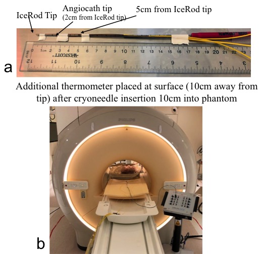
Figure 1. Experimental setup.
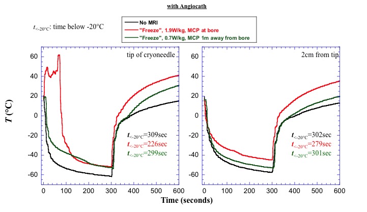
Figure 2. Plots shown impact of MRI on temperature during a 10 minute freeze-thaw cycle when the cryoneedle was inserted inside an angiocath.
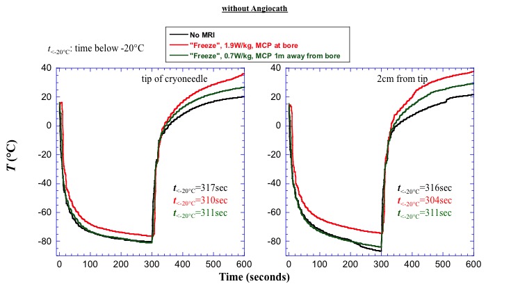
Figure 3. Plots shown impact of MRI on temperature during a 10 minute freeze-thaw cycle when the cryoneedle was inserted directly into the phantom without an angiocath.