4134
Active Shimming of Metallic Probes for Interventional MRI1Department of Radiology, Vanderbilt University Institute of Imaging Science, Nashville, TN, United States
Synopsis
Artifacts caused by large magnetic susceptibility differences between metallic probes and the surrounding tissue are a persistent problem in interventional MRI. In 2019, we presented the concept, design and modeling of active shims for metallic probes inspired from naval degaussing systems. Field disturbance induced by a metallic probe at 3 Tesla was modeled and an active shim insert design was presented to shim the field variation around the probe. In this abstract we present the first experimental results showing effective recovery of metallic probe induced signal loss at 3 Tesla.
INTRODUCTION
Metal probe artifacts, primarily signal loss stemming from the large difference in susceptibility between metal and the surrounding tissue have long presented a challenge in Interventional MRI (IMRI)1-3. These artifacts obscure targets in biopsies4 and prevent accurate image-based monitoring in therapeutic applications5. The goal of this work is to introduce a solution to this problem by developing active shim coils to correct the field disturbance caused by the probe. In this abstract we present the first experimental results showing effective recovery of probe induced signal loss at 3 Tesla.METHODS
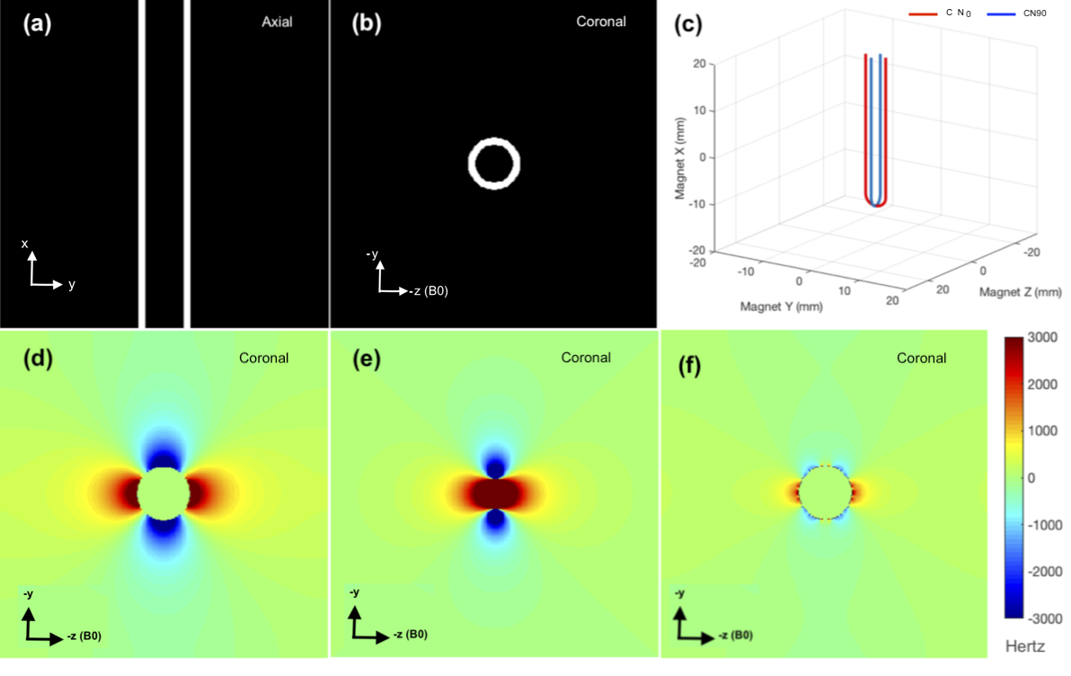
Our technique is inspired from degaussing coil technology used in ships and submarines for defense against magnetic field sensing sea mines6, as well as recent work in local shim coils for brain MRI7-9. In our earlier work, we demonstrated effective correction of the ΔB0 outside a titanium probe using a two-coil shim insert in simulations10. Here, we modeled and fabricated such a two-coil system for in scanner experiments.Simulations: We modeled a 6.35/4.57 mm OD/ID thick wall Titanium rod (Volume Susceptibility: 𝟀 = 182*10-6 ) in a surrounding medium of Water (𝟀 = -9.05*10-6 )11. The rod was defined within a 40 mm3 (4003 voxels, voxel resolution of 0.1 mm) grid of points in Matlab (Figure 1a, b). The induced ΔB0 was estimated with the rod orientated vertically, perpendicular to B0 , using Fourier-analysis based field calculation at 3 Tesla12-14. Next, a two coil shim insert was modeled using 26 gauge (0.4 mm) wire to fit inside the rod. The coils labeled CN0 and CN90 were designed orthogonal to each other with simple rounded tip geometries (Figure 1c). The numbers indicated the angle in the Needle’s radial direction. 1 Ampere Bz fields generated by the coils were computed with a Matlab implementation of Biot Savart’s law15. Finally, shimming was simulated by fitting the rod induced ΔB0 with the coil fields in an unconstrained least squared fit.
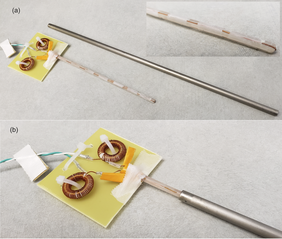
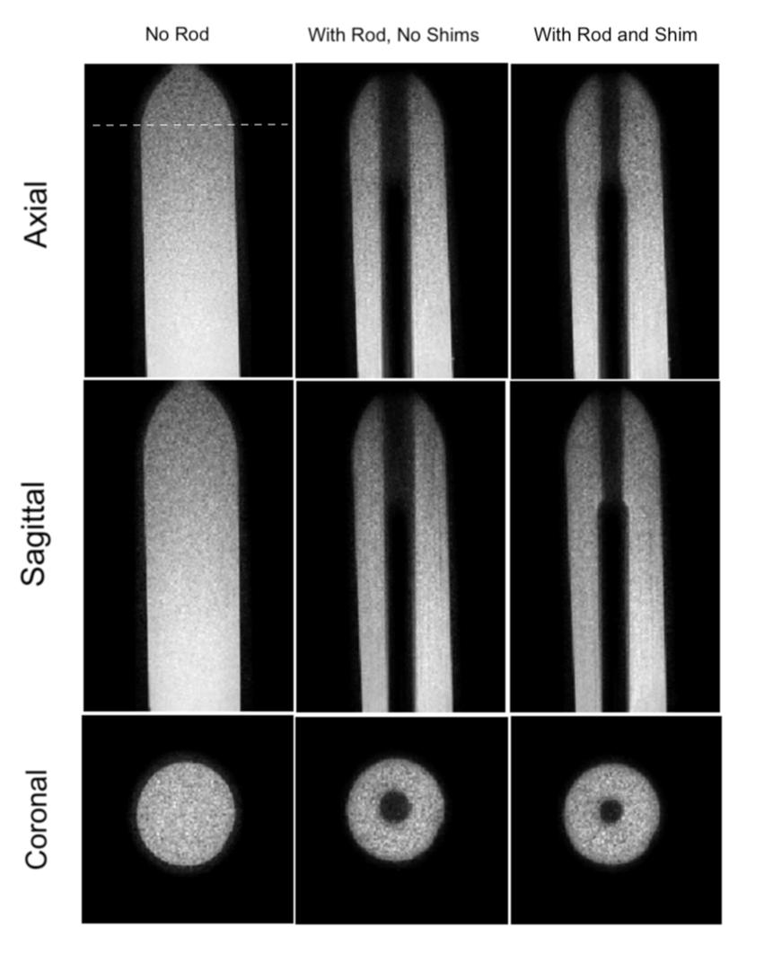
Experiments: A 12-inch CP Grade 2 hollow Titanium rod (Titanium Processing Center, MI, USA) with the same OD/ID as above was used for the experiments. For the shim insert, a 12 cm long 4 mm cylindrical former with four 0.8 mm diameter grooves for shim wire placement was 3D printed. 26-gauge enameled copper wire was placed into the slots to form the two coils. The coils were insulated with a single layer of insulation tape. The shim set was connected to a constant current power supply (KeySight E3631A, Keysight Technologies, CA, USA) using 20 feet long twisted cables. Four inhouse made broadband Toroidal chokes (~25-30 dB S21 isolation @ 127 MHz) were placed in line with each shim coil to suppress RF and gradient induced voltages. All experiments were performed on a Philips Elition 3 Tesla scanner with a 2 channel transmit/receive body coil. The shim set was inserted into the titanium rod and the setup placed vertically in a water bottle phantom to match the simulation condition. 3D GRE imaging with field mapping (1 mm3 voxels, 240 x 96 x 96 mm3 FOV, TR/TE/ΔTE = 9.5/4.7/0.5ms, FA = 8o, Tacq = 100 s) was then performed in three conditions, phantom without any rod, with rod and no shimming, with rod and active shimming.
RESULTS
Figure 1 shows the setup and results of the simulations. Figures 1d and e show the Titanium rod induced ΔB0 and the 1 Ampere field produced by the CN0 coil. A similar dipolar pattern is observed in both, indicating the feasibility of shimming. Figure 1f shows the coronal slices across the shimmed field with a current of -1.5 Amps in CN0 and 0 Amps in CN90. Excellent compensation of the field is observed, indicating the potential of signal recovery around the rod. The central rod is masked in all fieldmaps.Figure 2a shows the Titanium rod, the shim insert with the two shim coils and a zoomed in view of the same (inset). The base plate of the shim insert holds the chokes. Figure 2b shows the insert placed inside the rod. This setup is placed vertically in the scanner, perpendicular to B0.
Figure 3 shows magnitude images in three planes of the bottle without the rod, with the rod but no shims and with -1.5 Amp CN0 shim. The 6.35 mm diameter Titanium rod produces a conspicuous signal void of greater than 20 mm in diameter. With shimming, the signal around the rod is recovered to a large extent in the upper section of the bottle where the insert reaches. The signal void shrinks to ~13 mm in diameter, i.e. a recovery of almost 58% of lost signal around the rod.
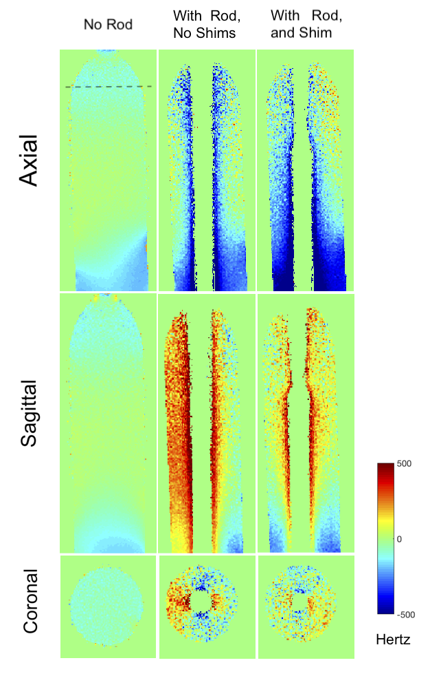
Figure 4 shows the fieldmaps in the same planes. Without shimming the bipolar ΔB0 pattern is observed around the signal void, which is minimized after shimming.
DISCUSSION
The results demonstrate that it is possible to shim and recover signal losses around metallic probes with active shim coils. Generalized coil paths can be designed to provide robust shimming for all probe orientations16. Shims can also be designed for probes with specific geometries, tip shapes and materials. Artifact reduction can be potentially achieved in a variety of qualitative and quantitative IMRI applications.Acknowledgements
This work was supported by NIBIB 1R21EB025258. I would like to thank Dr William A Grissom and Dr Megan Poorman for advice on field modeling.References
1. Weiss CR, Nour SG, Lewin JS. MR-guided biopsy: a review of current techniques and applications. J Magn Reson Imaging. 2008 Feb;27(2):311-25. PMID: 18219685 doi: 10.1002/jmri.21270.
2. Nour SG, Lewin JS Percutaneous biopsy from blinded to MR guided: an update on current techniques and applications. Magn Reson Imaging Clin N Am. 2005 Aug;13(3):441-64. PMID: 16084412 DOI: 10.1016/j.mric.2005.04.009
3. Butts K, Pauly JM, Daniel BL, Kee S, Norbash AM.Management of biopsy needle artifacts: techniques for RF-refocused MRI. J Magn Reson Imaging. 1999 Apr;9(4):586-95. PMID: 10232519
4. Kuhl CK, Morakkabati N, Leutner CC, Schmiedel A, Wardelmann E, Schild HH.MR imaging--guided large-core (14-gauge) needle biopsy of small lesions visible at breast MR imaging alone. Radiology. 2001 Jul;220(1):31-9.PMID: 11425969 DOI: 10.1148/radiology.220.1.r01jl0731
5. Xinyang Liu; Kemal Tuncali; William M. Wells; Gary P. Zientara. Automatic probe artifact detection in MRI-guided cryoablation. Conference: Proc. SPIE 8671, Medical Imaging 2013: Image-Guided Procedures, Robotic Interventions, and Modeling, 86712E DOI: 10.1117/12.2008530
6. Holmes JJ : Modeling a ship’s ferromagnetic signatures. ISBN 9781598292497
7. Juchem C, Nixon TW, McIntyre S, Rothman DL, de Graaf RA.Magnetic field homogenization of the human prefrontal cortex with a set of localized electrical coils.Magn Reson Med. 2010 Jan;63(1):171-80. PMID: 19918909 PMCID: PMC3046864 DOI: 10.1002/mrm.22164
8. Stockmann JP, Witzel T, Keil B, Polimeni JR, Mareyam A, LaPierre C, Setsompop K, Wald LL.A 32-channel combined RF and B0 shim array for 3T brain imaging.Magn Reson Med. 2016 Jan;75(1):441-51. PMID: 25689977 PMCID: PMC4771493 DOI: 10.1002/mrm.25587
9. Truong TK, Darnell D, Song AW.Integrated RF/shim coil array for parallel reception and localized B0 shimming in the human brain. Neuroimage. 2014 Dec; 103:235-40. PMID: 25270602 PMCID: PMC4312247 DOI: 10.1016/j.neuroimage.2014.09.052
10. Sengupta S. Modelling of Active shimming of Metallic Needles for Interventional MRI. Proc of the 27th Annual Meeting of the ISMRM, Montreal, Canada, 2019. p 3841.
11. Schenck JF, The role of magnetic susceptibility in magnetic resonance imaging: MRI magnetic compatibility of the first and second kinds. Med Phys. 1996 Jun;23(6):815-50.
12. Salomir, R., de Senneville, B. D. and Moonen, C. T. (2003), A fast calculation method for magnetic field inhomogeneity due to an arbitrary distribution of bulk susceptibility. Concepts Magn. Reson., 19B: 26–34. doi:10.1002/cmr.b.10083
13. Marques, J.P. and Bowtell, R. (2005), Application of a Fourier-based method for rapid calculation of field inhomogeneity due to spatial variation of magnetic susceptibility. Concepts Magn. Reson., 25B: 65–78. doi:10.1002/cmr.b.20034
14. Ramm, Paul, PhD Thesis, Universität Regensburg 2012. https://epub.uni-regensburg.de/20948/.
15. Masullo A https://www.mathworks.com/matlabcentral /fileexchange/42237-biot-savart-direct-integration-on-a-generic-curve
16. M. Poole, D. Green and R. Bowtell. Shoulder-Slotted Insertable Gradient and Shim Coil Set. Proceedings of the International Society for Magnetic Resonance in Medicine, 16, 1165, (2008).
Figures