4122
Designing RF Screens for MRI guided Fucused Ultrasound Applications
Rock Hadley1, Henrik Odeen2, Robb Merrill2, Sam Adams2, Viola Rieke2, Allison Payne2, and Dennis Parker2
1Radiology and Imaging Sciences, University of Utah, Salt Lake City, UT, United States, 2University of Utah, Salt Lake City, UT, United States
1Radiology and Imaging Sciences, University of Utah, Salt Lake City, UT, United States, 2University of Utah, Salt Lake City, UT, United States
Synopsis
This work evaluates screens with different hole size in their ability to pass ultrasound and their ability to shield RF in a Transcranial MR guided Focused Ultrasound experiment. Hydrophone and radiation force balance studies were used to measure attenuation and peak pressure when passing ultrasound through the screens compared to water-only measurements. Electromagnetic simulations and MRI experiments were performed to measure RF shielding effectiveness of the screens by comparing their ability to change known artifacts in a transcranial transducer compared to a solid conductor.
Introduction
The ground plane of focused ultrasound transducers often distorts the imaging (B1) RF field. For example, the RF field patterns in the hemispherical transducer in one commercially available 3 Tesla Transcranial Magnetic Resonance guided Focused Ultrasound (TcMRgFUS) system (Exablate, Insightec, Isreal), causes an artifactual low signal band of near the transducer focal point (see Figure 1), reducing temperature measurement accuracy. We have demonstrated recently that this band can be shifted or eliminated and the SNR at the ultrasound focus can be greatly increased by applying a screen that blocks RF magnetic fields while being transparent to the 650-kHz ultrasound field. Here we study the performance of RF screens of different mesh sizes for applications where RF energy must be blocked and ultrasound energy passed.Methods
Screens of different hole sizes were evaluated with hydrophone and Radiation Force Balance (RFB) testing for ultrasound attenuation and beam spreading. RF electromagnetic properties were compared using simulations and verified with MR experiments. Screens included a commercial Bronze wire screen with 2-mm hole size and several tinned copper wire screens that were made in-house with 1-, 2-, 3-, and 4-cm hole sizes, (see figure 2). All were 30awg wire. Hydrophone and RFB measurements were made using a 256-element 14.4x9.8-cm aperture ultrasound transducer (Image Guided Therapy, Pessac, France/Imasonic, Voray-sur-l'Ognon, France) with a 10-cm focal length and operating at 940-kHz. Hydrophone scans were performed at the focal point plane with screens positioned 4-cm from the focal spot. Electromagnetic simulations were performed using CST Studio Suiteâ (CST). The Insightec neuro transducer was modeled as a solid 30-cm diameter semi-spherical conductive ground plane filled with water. Screens of 24-cm diameter were positioned at 8-cm from the water surface. A 16-rung birdcage coil created a 123-MHz circularly polarized excitation field. Maximum B1- values were used to analyze trends in screening effectiveness vs. mesh size with comparison to a simulated solid copper disk (0.25-mm thick) used as the simulation gold standard. MR imaging studies were performed to determine the ability of the screens of different hole sizes to change the original transducer artifact. Screens were cut to 24-cm diameter and positioned in an Insightec neuro transducer oriented in the upward facing preclinical position. The transducer was filled with tap water and screens were positioned 7.5-cm deep on a plastic support resting on the bottom of the transducer. Axial and sagittal GRE images (TR/TE/Flip=123/4/70°) were acquired for each screen and compared with images using an aluminum disk (gold standard).Results
Results for the hydrophone studies (Table 1) show the 2-mm commercial screen had approximately 7% attenuation at 940-kHz compared to water-only. The screens with mesh size 2-cm or larger had less than 1% attenuation and were essentially ultrasound transparent. RFB data (Table 2) confirms the hydrophone results showing that 99% of the power is transmitted through a screen with a hole size of at least 2-cm. Simulations results, (Figure 3), demonstrated artifacts that are problematic in 3T imaging with this transducer geometry and the way these artifacts change with mesh hole size. Rather than eliminate artifacts caused by this transducer, the goal of this study was to compare RF screening capabilities of different screens with the solid copper or aluminum disk. These results show that the 1-cm mesh creates a fairly effective RF screen and provides an imaging result similar to the copper disk. The screens with larger mesh sizes progressively let more RF energy through the screen and the original artifact progresses to its original position as mesh size increases. The MR imaging results (Figure 4) demonstrate similar trends as the simulation results. It can be seen that the 2-mm mesh closely approximates the aluminum disk, however, with a mesh size of 2-cm and larger, the original artifact begins to return, indicating an increasing ineffectiveness at RF screening with larger mesh size compared to a solid conductor.Discussion
The ultrasound through transmission and the RF simulation and MRI experiments demonstrate the effects of a screen mesh size in ultrasound transmission and RF screening in an MRgFUS environment. In comparing the RF screening capabilities of the different screens relative to a solid copper or aluminum disk, these results show that the 1cm mesh creates a fairly effective RF screen and provides an imaging result similar to the solid disk. The screens with larger mesh sizes progressively let more RF energy through the screen and the original artifact progresses to its original position as mesh size increases. These results indicate that a mesh size of 2-cm or greater is nearly transparent to ultrasound at 950kHz and that a mesh size of 1-2-cm or smaller provides similar RF shielding properties as a solid conductor. It’s important to note that ultrasound transmission results are frequency dependent and a smaller hole size may perform better for ultrasound transparency in a lower frequency transducer.Conclusion
Given the tradeoff between the use of larger screen mesh for better ultrasound transmission and smaller mesh size for RF screening, these results indicate that a mesh size on the order of 1-2-cm may be the best compromise for US transmission and RF screening purposes for ultrasound at 940-kHz and 3Tesla MRI (123-MHz), respectively.Acknowledgements
Mark H. Huntsman Endowed Chair at the University of Utah and NIH grant 1R01 EB028316References
No reference found.Figures
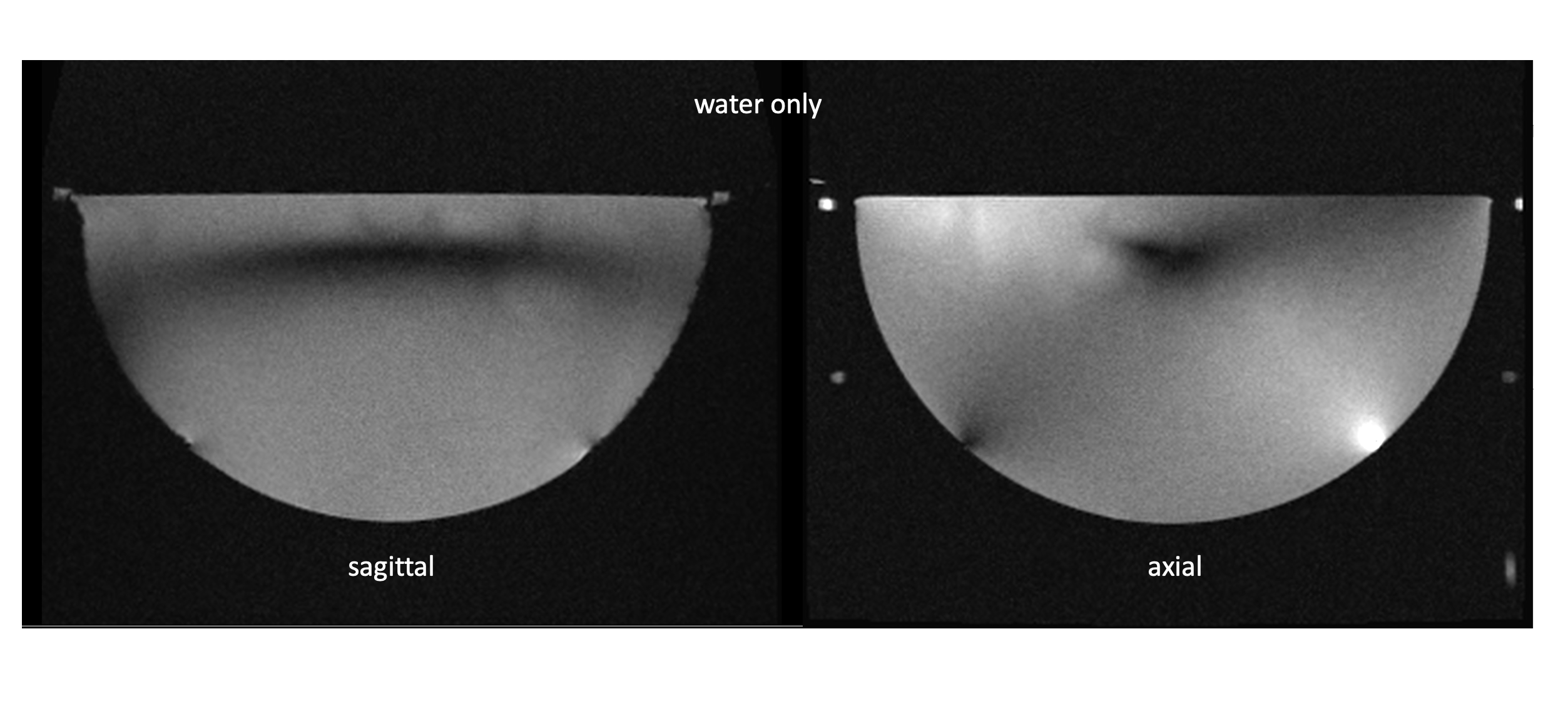
Figure 1: MRI image
banding artifacts of a 30-cm diameter Insightec Neuro Transducer in
pre-clinical position using a Siemens 3T Skyra MRI system operating at 123 MHz.
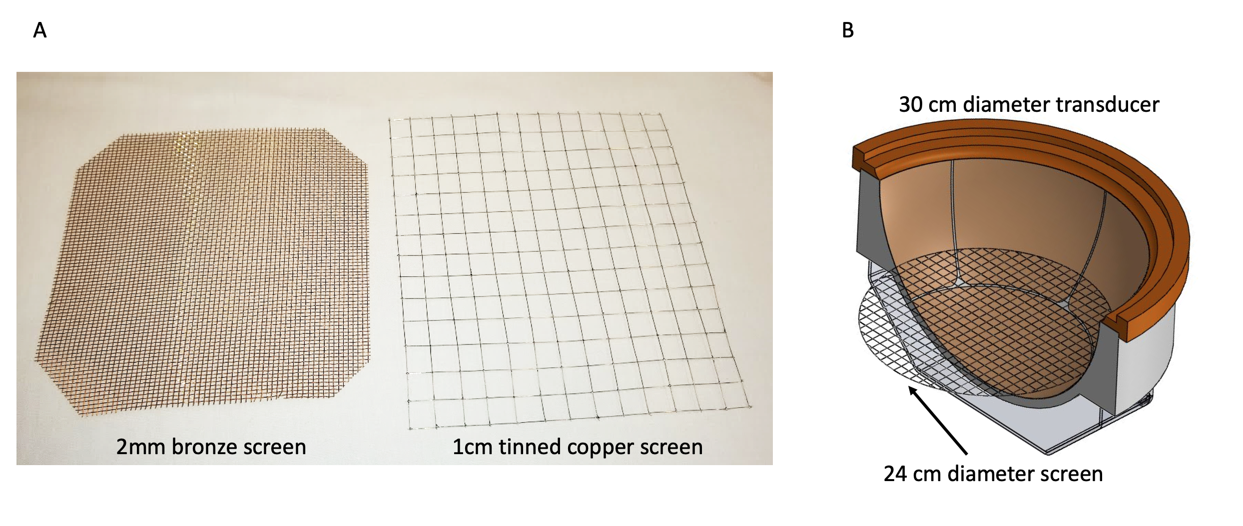
Figure 2: A) Screens
used in this study included a 2-mm mesh bronze screen and a 1-cm mesh tinned
copper screen. Both screens were made
from 30 awg wire. Wire crossovers are
connected by pressure in the 2-mm screen and with solder connections in the
home-made 1-cm screen. B) Insightec Neuro Transducer in the pre-clinical
position with a 24-cm diameter screen positioned in the transducer as in the
CST simulations and MRI measurements of this work.
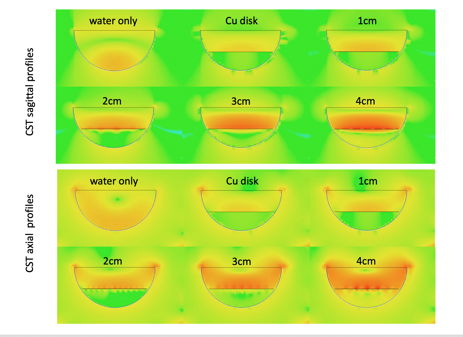
Figure 3: CST
simulation results for the different screen mesh sizes in a pre-clinical mode
solid ground plane transducer. The water-only
simulations demonstrate the artifact associated with the transducer in a 123
MHz MRI imaging study.
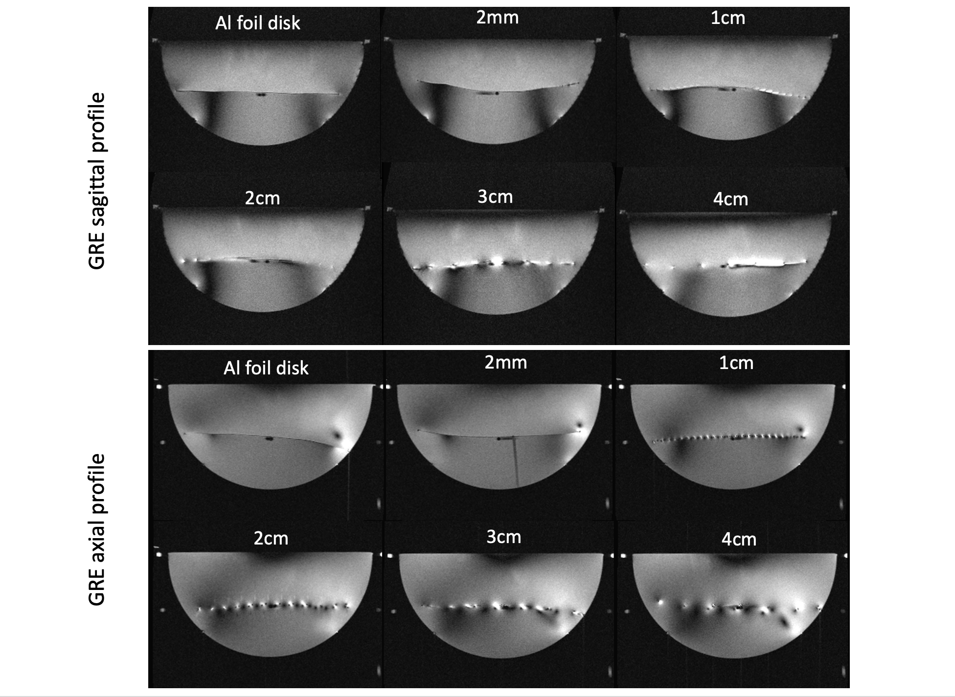
Figure 4: MRI imaging
results using the Insightec Neuro Transducer, in pre-clinical position, on a
Siemens 3T Skyra MRI. The sagittal images show that with increasing mesh size,
the banding artifact begins to come back into the volume of the
transducer. Similarly, the axial images
show the central region of no signal sensitivity begins to move back towards
its original location with increasing mesh size.
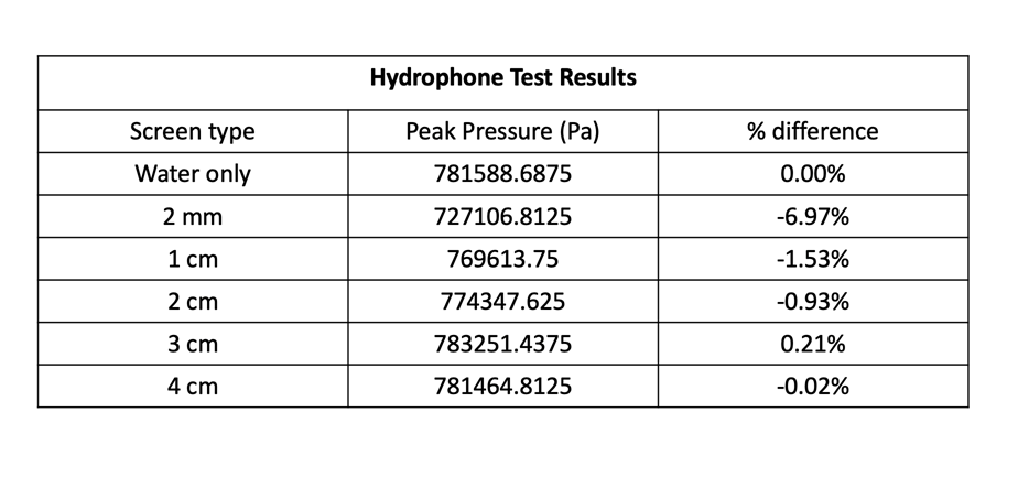
Table
1: Hydrophone test measurements
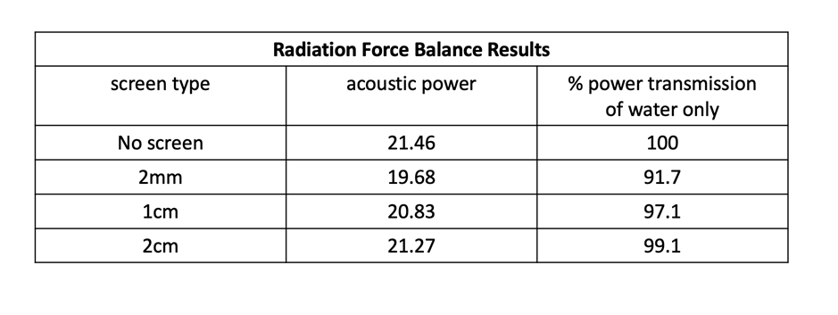
Table 2: Radiation force balance measurements