4108
Comparison of a 3-channel 31P array to a single loop coil for cardiac MRS at 7 T1Center for Medical Physics and Biomedical Engineering, Medical University of Vienna, Vienna, Austria, 2IKEM, Institute for Clinical and Experimental Medicine, Praha, Czech Republic, 3Technical University of Liberec, Liberec, Czech Republic
Synopsis
Cardiac 31P MRS is a powerful noninvasive tool in the assessment of myocardial energy metabolism, but it is inherently limited by low SNR, which can be mitigated by increasing B0. In order to fully exploit the SNR gain, elaborate RF coil development is necessary. In this work we compare the performance of a standard single loop coil with an optimized 3-element array in simulation and measurement. We validated the superior performance of the array experimentally, with a 2.2-fold SNR increase in localized spectroscopy, and in simulation yielding a 1.7 and 2.2 times higher PE and SE for the array, respectively.
Introduction
Cardiac phosphorous (31P) magnetic resonance spectroscopy (MRS) is a powerful noninvasive tool in the assessment of myocardial energy metabolism. Metabolites such as ATP and PCr are readily detectable in 31P spectra and their relative and absolute concentrations are strong indicators of cardiac dysfunction with ischemic events as a major cause. 31P MRS is inherently limited by low SNR, which can be mitigated by increasing B0. In order to fully exploit the SNR gain, elaborate RF coil development is necessary due to increased magnetic field inhomogeneities, RF non-uniformities and power deposition constraints associated with the increased static magnetic field. In this study we compare the performance of a commercially available standard single loop 31P coil with a specifically optimized 3-element 31P array in simulation and measurement.Methods
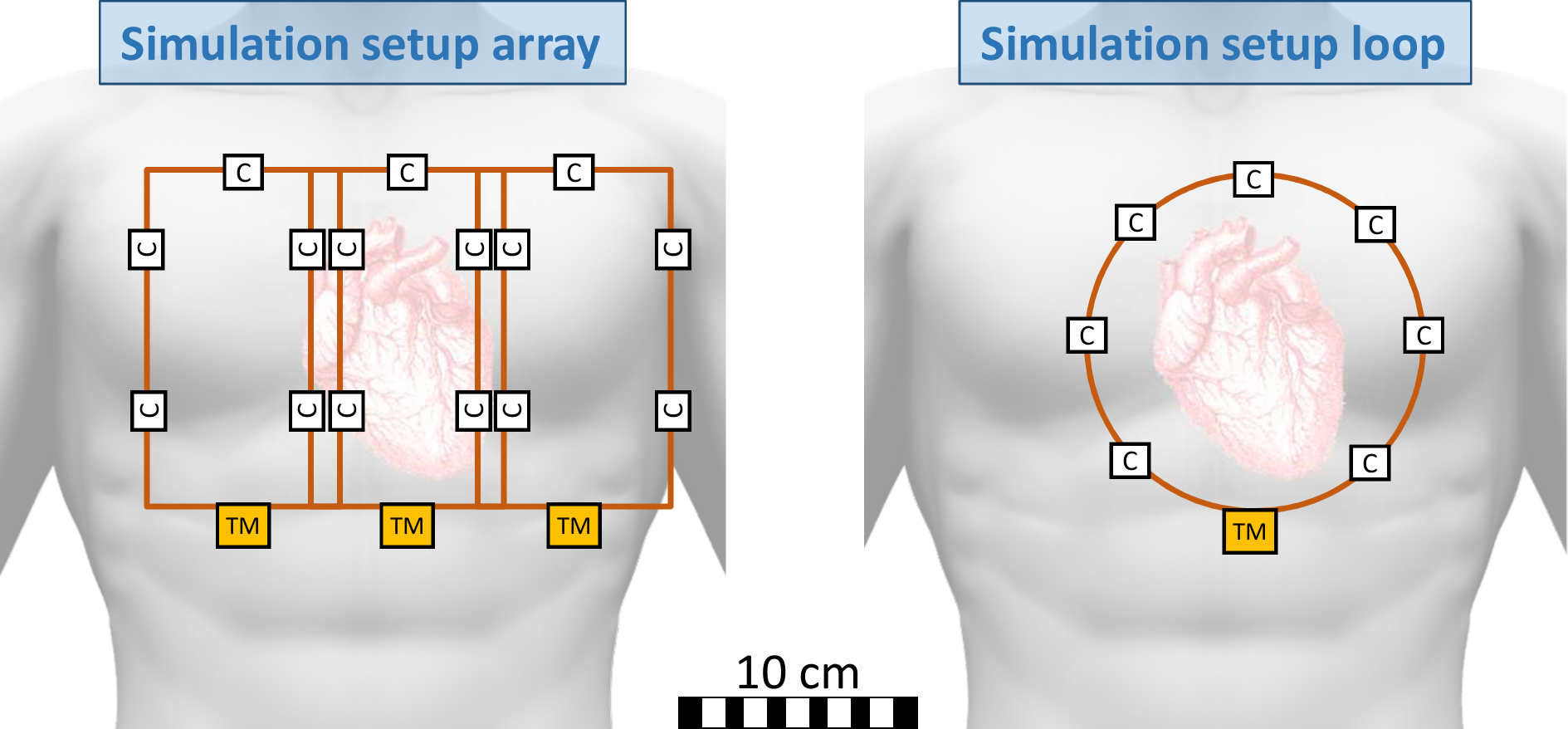
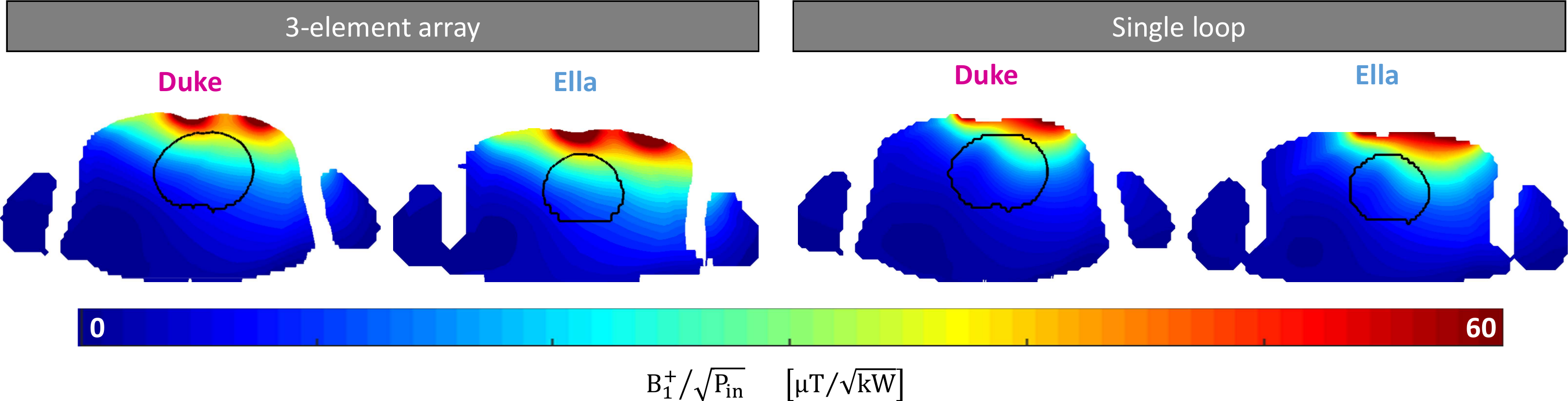
3-element coil implementation: Suitable RF coil designs for the 31P array were investigated via 3D electromagnetic simulation in a comprehensive simulation study (1), resulting in a theoretical superiority of a 3 element array design with an element size of 9.4x14.1 cm2 positioned centered over the heart. To increase electromagnetic coupling of the RF coil, the 31P array was constructed out of flexible litz wire (∅=2 mm) and a fixed overlap for nearest neighbor decoupling. 1H and 31P coil cross talk is minimized by replacing every second segmenting capacitor by an LCC trap (2), resulting in three traps per element. Performance of the 31P array was tested on the bench measuring S-parameters for 5 human volunteers (3m/2f) using a vector network analyzer (E5071C, Agilent, Santa Clara, CA, USA).3D electromagnetic simulation (EMS): Both RF coils were simulated in XFdtd 7.5. (Remcom, State College, PA, USA). The single loop has a diameter of 140 mm, according to the vendor’s user manual, and an assumed wire thickness of 1.5 mm. An RF co-simulation approach was used to enable fast tuning and matching in ADS (Keysight Technologies, Santa Rosa, CA, USA) (3) by replacing all lumped elements in the 3D EMS with 50Ω voltage sources. Realistic loss estimations for capacitances, and solder joints were modeled as series resistances. Both RF coils were loaded with two realistic human body models (“Duke” & “Ella”, Virtual Family, IT’IS Foundation, Zurich, Switzerland). Post-processing of 3D EM data and co-simulation results was performed in Matlab 2017b (Mathworks, Natick, MA, USA). The simulation setup of both coils can be seen in Fig. 1.
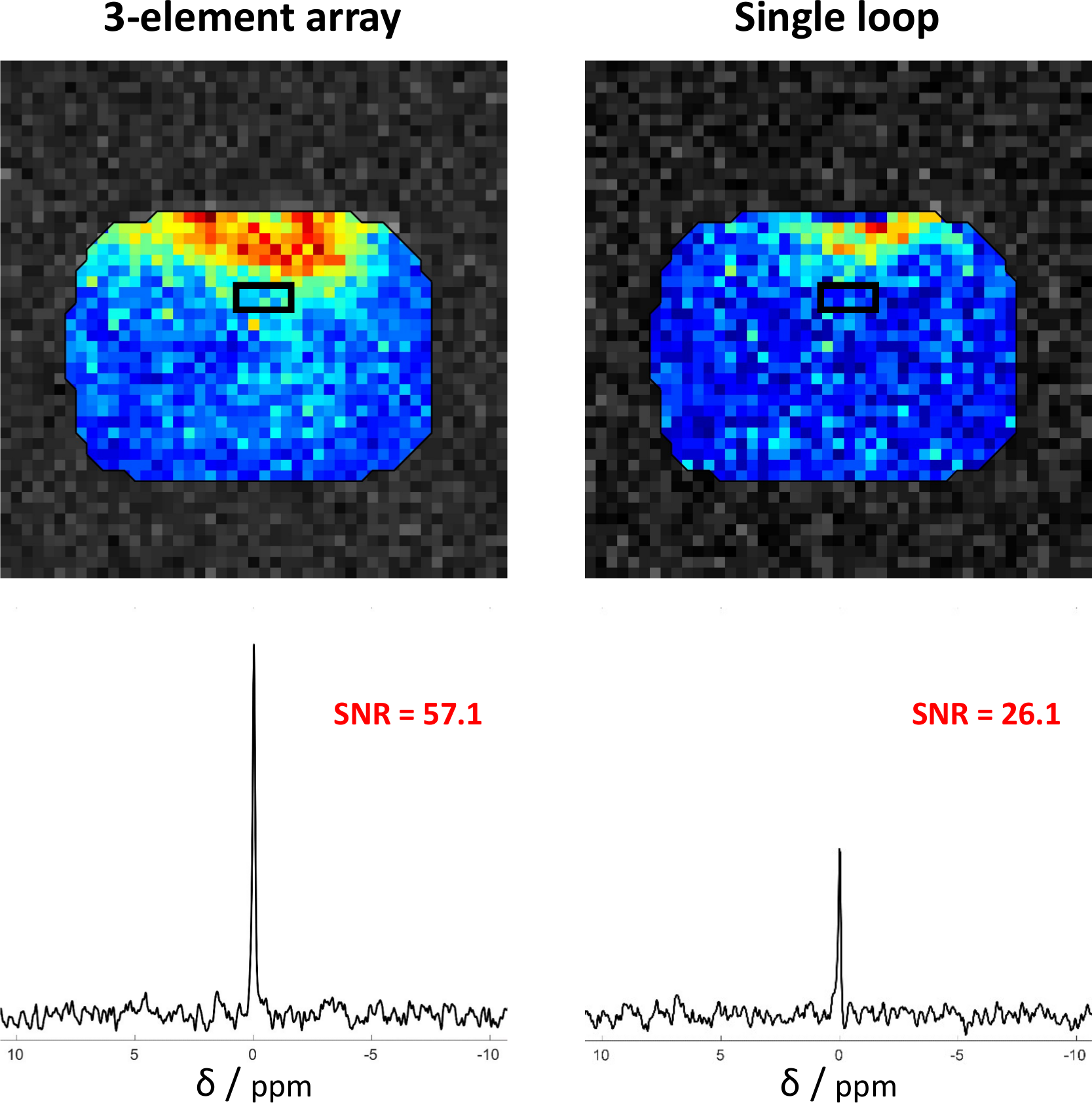
MR measurements: All MR measurements were conducted on a 7 T MR scanner (Siemens Magnetom, Erlangen, Germany). The coils were loaded by a phantom with dimensions of 23x28x38 cm3 containing saline solution (σ ≈ 0.5 S/m, ε ≈ 80) with 1.57 g/L K2HPO4 and 0.14 g/L KH2PO4. The RF coils were positioned centrically with respect to the phantom which was located in the isocenter of the scanner. In this setup 31P images as well as localized spectra were acquired. 31P imaging sequence: TrueFISP, TR/TE = 8/4 ms, 4 slices (20mm), 96 avg. 31P spectroscopy sequence: STEAM, TR/TE = 3000/13.4 ms, TD = 6.9 ms, voxel size 5 x 2 x 5 cm3, 16 avg, voxel location: 7 cm from phantom wall (see Fig. 2). The voxel was set at this distance to match the coil-heart distance in reality.
Results
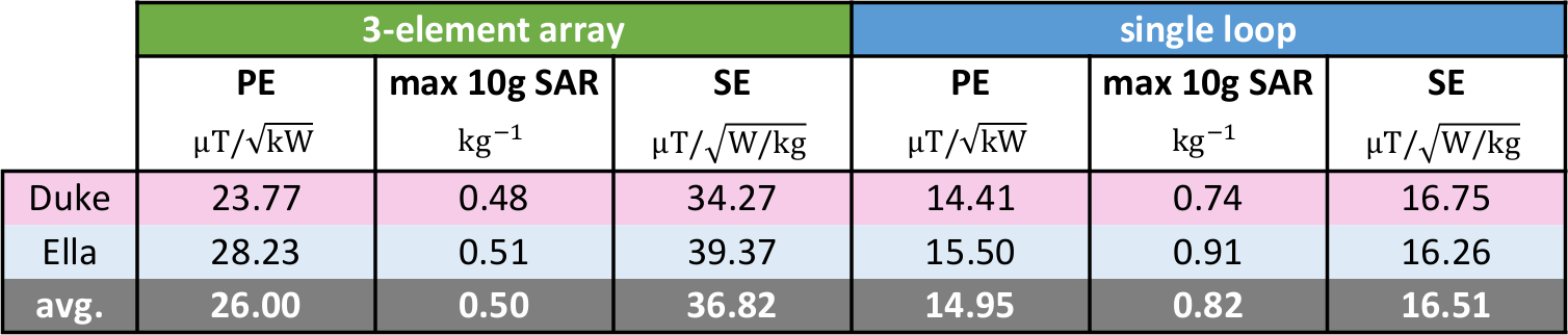
Bench measurements show sufficient matching and isolation between array elements (Sii ≤ -19.9 dB and Sij ≤ -14.9 dB averaged over 5 volunteers). MR measurements show a 2.2-fold SNR within the voxel of interest (see. Fig. 2) and an overall higher coverage of the top part of the phantom (see. Fig. 2 top), when comparing the 3-element array with the single loop. The simulation results can be seen exemplarily for a transversal slice through the heart for each of the simulation setups in Figure 3 and are summarized in Table 1. The averaged values over “Duke” and “Ella” for power efficiency (PE) and SAR efficiency (SE) shows a 1.7 and 2.2 fold higher PE and SE, respectively, for the 3-element array.Discussion and Conclusion
In this work we present preliminary results of the implementation of a dedicated flexible 1H-31P RF coil for cardiac MRS investigations at 7 T. Comparison with a commercially available standard loop coil shows superior performance of the developed 3-element array in simulation and measurement. The results shown within this work justifies very well the additional effort that has to be undertaken when designing and building array coils vs single loops.Acknowledgements
This work was funded by the Austrian Science Fund (FWF) grants P28059 and P28867References
1. Goluch-Roat S, Vit M, Schmid AI, Laistler E. Simulation comparison of 28 different 31P arrays for cardiac MR spectroscopy at 7 T. In: Proceedings of the ISMRM 2019.
2. Meyerspeer M, Roig ES, Gruetter R, Magill AW. An improved trap design for decoupling multinuclear RF coils. Magn Reson Med 2013;00 doi: 10.1002/mrm.24931.
3. Kozlov M, Turner R. Fast MRI coil analysis based on 3-D electromagnetic and RF circuit co-simulation. J Magn Reson 2009;200:147–52 doi: 10.1016/j.jmr.2009.06.005.
Figures