4106
Fixed Geometry 28-Channel Array for Full Head Coverage of Hyperpolarized 13C MRS1Department of Health Technology, Technical University of Denmark, Kgs. Lyngby, Denmark, 2Department of Electrical Engineering, Technical University of Denmark, Kgs. Lyngby, Denmark
Synopsis
We describe the design and performance of a 28-channel RF receive array optimized for human head 13C imaging at 3T. The array employs a fixed and symmetric cylindrical geometry to provide predictable prior information of the coil sensitivity profiles, which can be used to resolve practical challenges of hyperpolarized parallel imaging and to improve performance. The results show good SNR and spatial encoding of the different elements, with only small performance difference between the individual elements.
Introduction
Hyperpolarized 13C metabolic imaging may be a decisive tool to better understand the human brain, both in health and disease 1,2. Metabolic imaging using hyperpolarized substances requires accurate quantification of conversion rates, in order to extract the very detailed metabolic information that these experiments can provide. Accelerated acquisition by means of parallel imaging can assist in achieving this, which means that accurate information about the sensitivity profiles of the RF receive coil is needed. However, the low natural abundance of 13C and its low gyromagnetic ratio makes it very challenging to accurately estimate the sensitivity profiles from in-vivo measurements.In this context, having a rigid coil geometry can be helpful, since sensitivity profiles can be estimated a-priori with high accuracy. Additionally, at low frequency, due to the higher proportion of electronic noise (compared to sample noise), high-performance rigid coil geometries can be advantageous, despite of their inferior anatomical fitting. Initial results of such design approach, together with parallel imaging have already been successfully implemented for pig kidney 13C MRS 3. In this work we propose a coil array following this design approach for human head imaging, and evaluate its coverage across the full FOV. Comparison to a commercial array is also provided as reference.
Materials and Methods
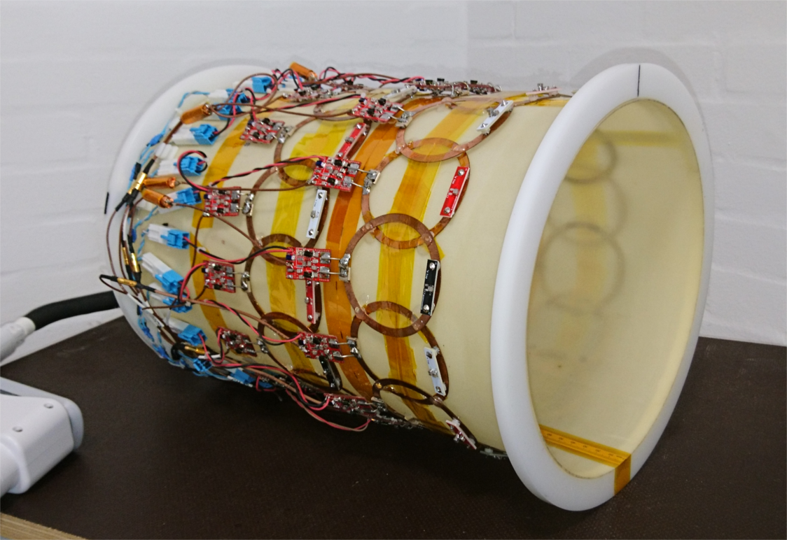
Coil DesignThe design of the array individual elements is based on previous work using non-segmented coils, where the entire circuitry (including tuning-matching-detuning) is integrated on a single board 4. The coils are made of flattened copper wire (6 mm x 0.7 mm cross section) with an outer diameter of 82 mm. 1H traps were added using part of the coil to improve compatibility with external 1H coils (needed for anatomical mapping to support 13C metabolic imaging). The measured unloaded-to-loaded Q-ratio for the individual elements is QU/QL=420/60 for human loading. In order to reduce mutual coupling between next-neighbouring elements, highly mismatched preamplifiers are used following the design approach described in 5, in order to reach decoupling levels beyond 30 dB.
The array is formed by two coil rows 14 channels each, placed on a cylindrical coil holder with inner bore diameter of 252 mm and 2 mm of thickness. The edge-to-edge separation between coil rows is 25 mm. This arrangement allows a coverage across the z-axis of approximately 190 mm, which is sufficient for whole head imaging. The limited number of 13C channels available at the used MR scanner (32 channels) contributed to the design choice of separating the coil rows (and not overlapping them) in order to extend the coil array FOV over the z-axis.
MR Experiments
13C MRS measurements (CSI, 360x360x20 mm3, matrix size = 24 x 24) were performed on a cylindrical ethylene glycol phantom (250 mm diameter, 200 mm long) doped with 17g/L of NaCl, in order to emulate tissue loading. Three different axial measurements were acquired at different slice locations on the z-axis. The first location (Z = 54 [mm]) corresponds to a slice centered at the front row of coils, the second location (Z = 0 [mm]) corresponds to the array geometrical center, and the third location (Z = -54 [mm]) corresponds to a slice centered at the back row of coils. An additional measurement using a commercial 8-channel array was performed as reference to a state-of-the-art coil array.
Results and Discussion
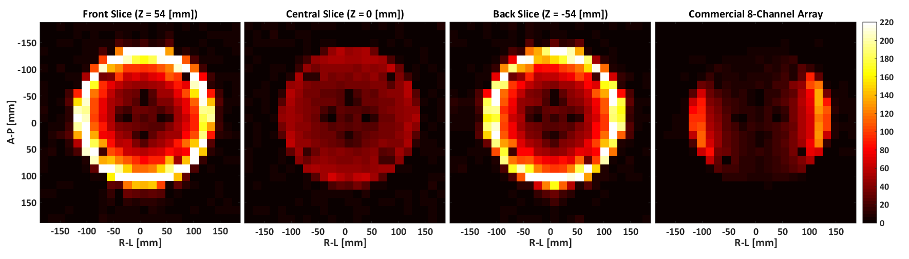
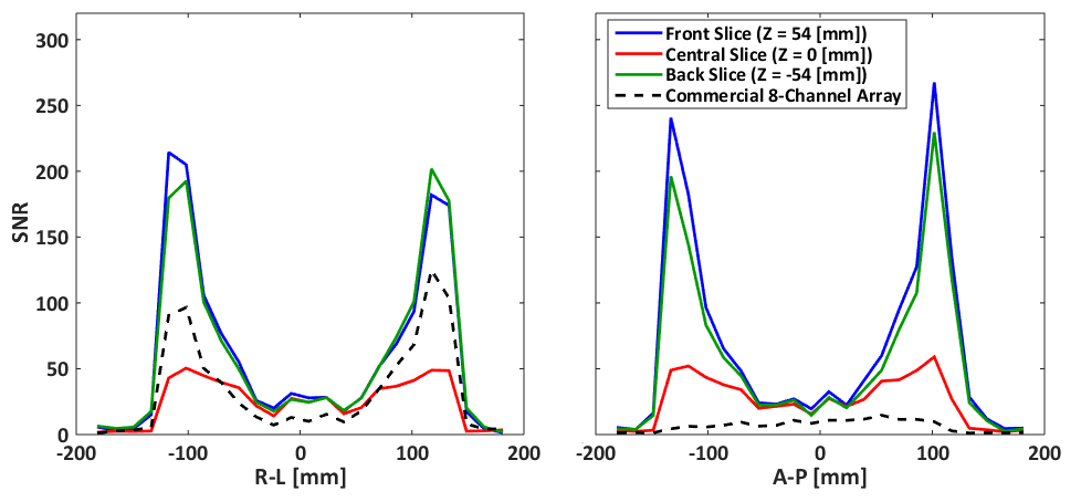
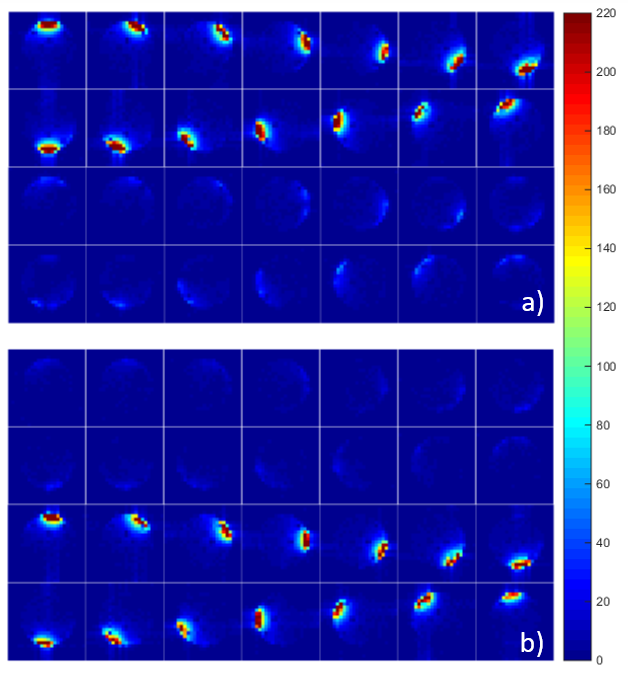
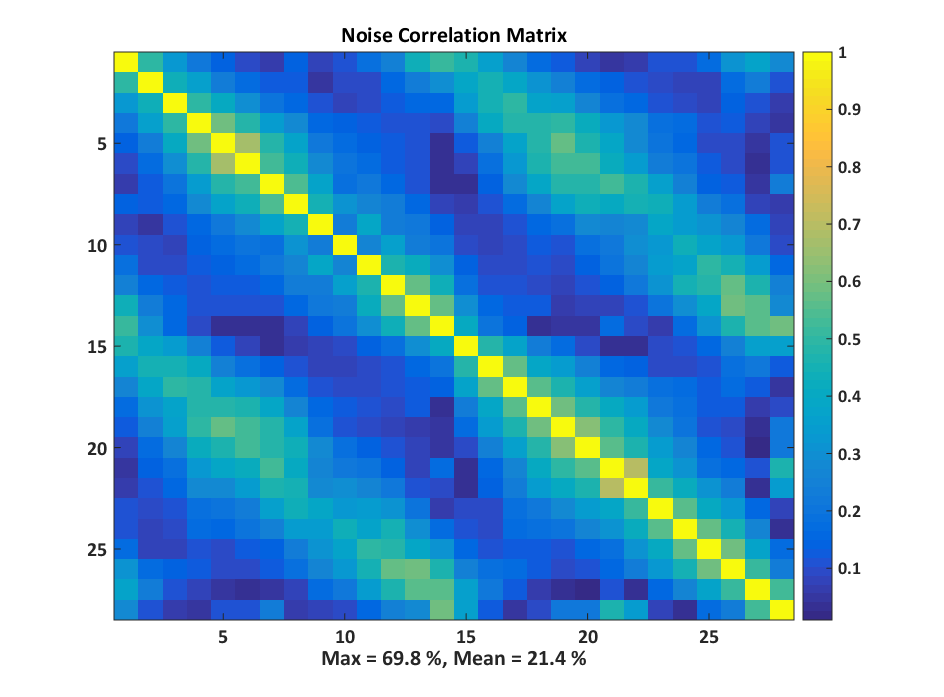
The acquired SNR maps are presented in Figure 2. They are based on three different measurements done with the fabricated 28-channel array, and the reference measurement with the commercial array. Figure 3 shows the SNR profiles across two orthogonal axes of the acquired slices. The results show good SNR symmetry across the whole slice. Also the difference between the front and back slices is minimal, showing that both rows of coils perform very similarly. As expected, the superficial SNR at the central slice is lower, but this difference decreases with the phantom depth, ultimately reaching the same SNR at the central part of the phantom. This result shows that the SNR across the z-axis for deep parts of the phantom is very similar, and that the array can effectively cover the whole FOV. The comparison to the commercial array shows an overall higher SNR of the fabricated array, both at the surface and at depth.Figure 4 shows the individual SNR maps of each coil elements for the two slices centered at the coil rows. The measured SNR is very similar for all array elements, both within the same row and between the different rows. Finally, Figure 5 shows the noise correlation matrix of the array, where some relatively high values are obtained, especially between some neighboring coils. These values, however, do not compromise the overall performance of the array.
Conclusion
A dedicated 28-channel coil array for 13C has been designed and fabricated. Measurements showing its performance over an FOV sufficient to cover a whole human head are shown. The design approach uses a fixed geometry, with large coverage along the z-axis by means of two rows of coils, which facilitates acceleration along that axis. The overall SNR performance is satisfactory compared to a commercial array, with the added benefit of the highly predictable sensitivity profiles due to the fixed geometry.Acknowledgements
No acknowledgement found.References
1. Miloushev VZ, Granlund KL, Boltyanskiy R, et al. Metabolic imaging of the human brain with hyperpolarized 13C pyruvate demonstrates 13C lactate production in brain tumor patients. Cancer Res. 2018. doi:10.1158/0008-5472.CAN-18-0221.
2. Grist JT, McLean MA, Riemer F, et al. Quantifying normal human brain metabolism using hyperpolarized [1–13C]pyruvate and magnetic resonance imaging. Neuroimage. 2019;189:171-179. doi:10.1016/J.NEUROIMAGE.2019.01.027.
3. Hansen RB, Sánchez‐Heredia JD, Bøgh N, et al. Coil profile estimation strategies for parallel imaging with hyperpolarized 13C MRI. Magn Reson Med. 2019;82(6):2104-2117. doi:10.1002/mrm.27892.
4. Sanchez-Heredia JD, Szocska Hansen ES, Laustsen C, Zhurbenko V, Ardenkjær-Larsen JH. Low-Noise Active Decoupling Circuit and its Application to 13C Cryogenic RF Coils at 3T. TOMOGRAPHY. 2017;3(1):60:66. doi:10.18383/j.tom.2016.00280.
5. Sanchez-Heredia JD, Johansen DH, Hansen RB, et al. Improved Decoupling for Low Frequency MRI Arrays using Non-conventional Preamplifier Impedance. IEEE Trans Biomed Eng. 2019;66(7):1940-1948. doi:10.1109/TBME.2018.2881203.
Figures