4105
A dual-frequency surface coil design comprised of a single loop for both proton and deuterium magnetic resonance imaging at 16.4T1Center for Magnetic Resonance Research, Department of Radiology, University of Minnesota, Minneapolis, MN, United States
Synopsis
X-nuclear MRS imaging (MRSI) plays critical roles in studying cellular energy metabolism in health and diseases. However, it requires one 1H coil for structural imaging and B0 shimming and another coil for X-nuclear MRS, leading to coil coupling and performance degradation. Here we developed a simple, low-cost technique to construct dual-frequency surface coil(s) operating at proton and X-nuclear frequencies. For the proof of concept, we conducted 1H MRI and 2H MRSI study at 16.4T; and more importantly, we made a two-channel dual-frequency transceiver coil array to demonstrate the potential for large volume imaging at ultrahigh field.
Introduction
X-nuclear (e.g., 31P, 17O and 2H) MRS imaging (MRSI) could play critical roles for better understanding neuroenergetics under various pathophysiological conditions1,2. Recently, we have developed a quantitative 2H MRSI technique to simultaneously assess cerebral glucose metabolism and TCA cycle activity at ultra-high-field (UHF)1,3,4. However, such studies require both 1H and 2H RF coils for structural and metabolic imaging. In traditional design, the electric decoupling between two coils often degrades the performance for the low-frequency X-nuclear imaging. Additionally, to construct a large size 1H surface coil operating at UHF, multiple split capacitors are commonly required1,2,5,6,7. In this abstract, we present a novel design of 1H-2H dual-frequency coil with single copper wire and a large coil size that can be tuned/matched to either 1H (~698 MHz) or 2H (~107MHz) Larmor frequency for imaging at 16.4T. Moreover, we demonstrate that the same principle can be extended to build multi-coil arrays with excellent performance.Methods
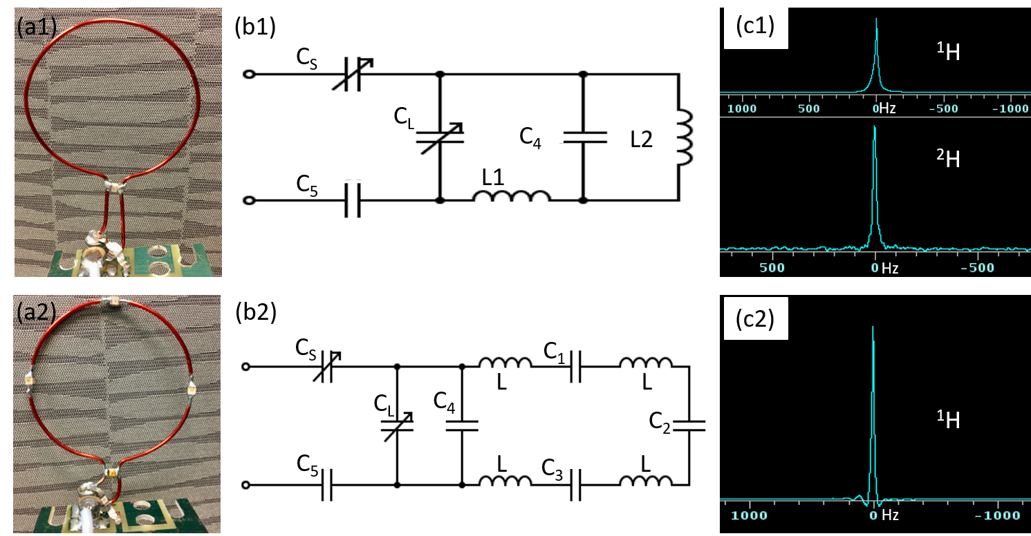
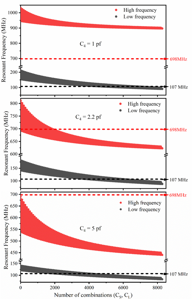
Figure 1(a1) shows the prototype of the 1H-2H dual-frequency coil which is based on the basic LC resonant circuit design and comprised of four capacitors and an open-loop (5.5 cm in diameter). Based on the circuit diagram shown in Fig. 1(b1), resonant frequencies (w0) of the coil can be estimated according to Eq. (1). With capacitance and inductance appropriately selected by simulation results (example shown in Fig. 3), frequencies near 698 MHz and 107 MHz can be obtained.$$ \frac{1}{\frac{1}{\frac{1}{\frac{1}{\omega_0L_1}-\omega_0C_4}+\omega_0L_2}-\omega_0C_L}-\frac{1}{\omega_0C_5}-\frac{1}{\omega_0C_S}=0. \qquad (1)$$
The coil was tested on a network analyzer to measure S-parameters at 698 MHz and 107 MHz, and afterward taken to phantom study at 16.4 T using a ~3.5 cm diameter water ball. Global proton FID was acquired (400μs hard pulse, NT=1, TR=2s) for power calibration. The 1H transmission field (B1) was mapped using the double-flip-angle method8 and 2D GE multiple-slice (GEMS) sequence (TR=6s, TE=2ms, matrix=64×64, FOV=48×48mm2, flip angle (FA)=20°&40°). A same-sized traditional 1H surface coil, split by four identical capacitors (1.3 pF each, see Figs. 1(a2) and (b2)), was used for comparison. Global deuterium FIDs were also collected (200μs hard pulse, NT=50).
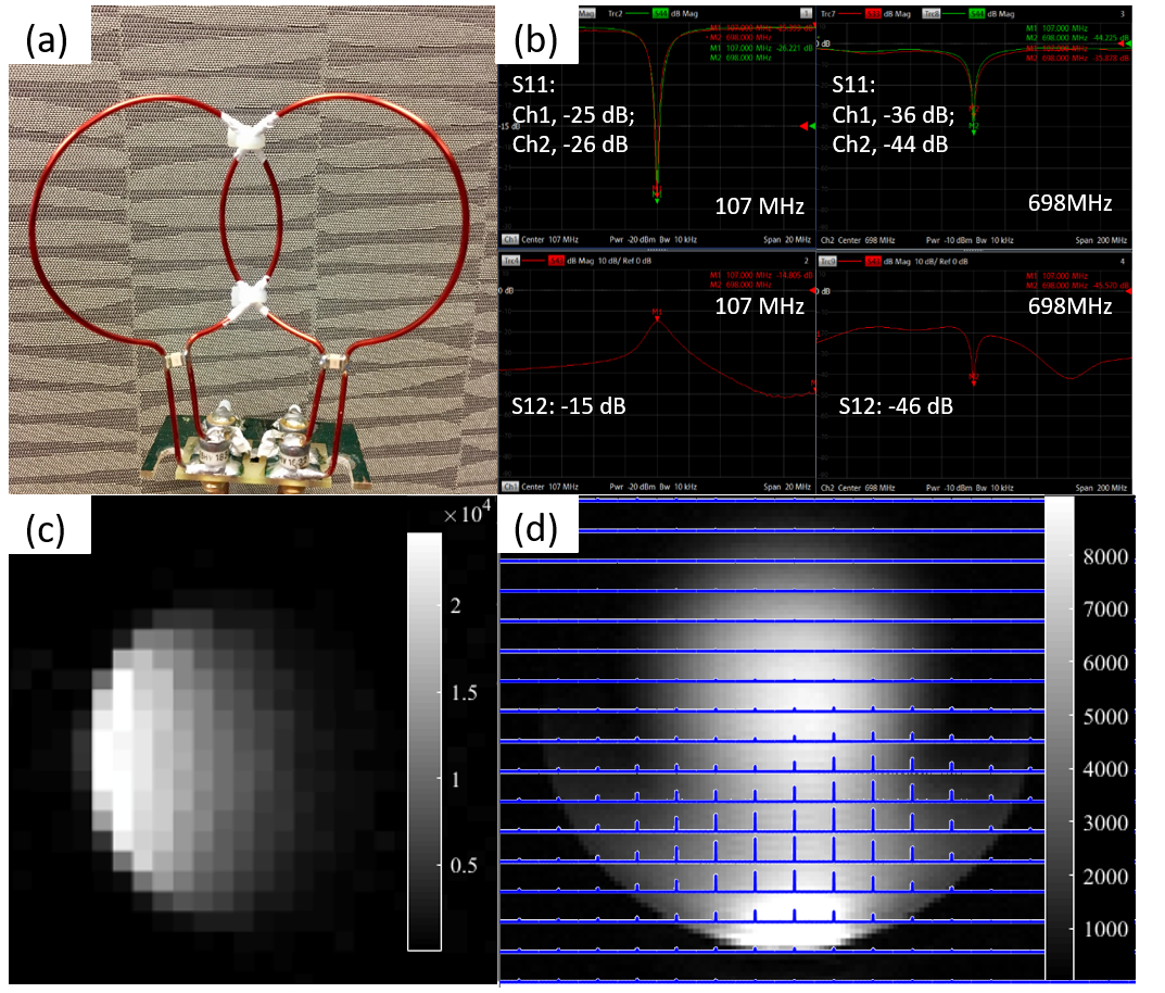
To test array coil design, we built a quadrature coil (Fig. 2(a)), comprised of two identical 1H-2H dual-frequency single-loop coils as shown in Fig. 1(a1). The S-parameters were measured on the bench with a loaded phantom. 2D GEMS (FA=20°, matrix=128×128, FOV=80×80mm2) and 3D chemical shift imaging (CSI) (TR=45ms, matrix=9×9×5, FOV=80×80×80mm3) sequences were employed to acquire proton and deuterium images at 16.4 T using a 4.5-cm water ball containing 0.4% D2O and 77mM NaCl. A 2D-GEMS (TR=70ms, FA=14°, NT=64, matrix=32×32, FOV= 80×80mm2, one 80mm slice) deuterium image was also collected.
Results and Discussion
Figure 3 shows the simulation results of the unloaded 1H-2H dual-frequency coil with the balance capacitor C5 fixed at 4.7 pF, to illustrate three representative cases with varied C4 values from 1 to 5 pF. Interestingly, the coil resonant frequency with 1 pF C4 was too high and unable to reach 698 MHz for 1H MRI, or too low with 5 pF C4. In contrast, the C4 value of 2.2 pF provided an optimal tuning range for both 1H (698 MHz) and 2H (107 MHz) resonances.By analyzing global 1H FID results shown in Fig. 1(c1) and (c2) as a function of RF pulse power, we found that the dual-frequency coil efficiency was about 40~50% of that traditional coil. Figure 4 shows the coronal B1 maps of the dual-frequency coil (top) and traditional proton coil (bottom), indicating a similar uniformity but different field intensities produced by the two coils. The lower B1 field of the dual-frequency coil is due to the lower energy efficiency. Since the proton coil is mainly for structural imaging and shimming, the decreased B1 efficiency won’t undermine its utility for 2H MRSI applications.
Figure 2(b) shows the S-parameters of both 1H and 2H channels of the quadrature coil, suggesting that the two channels are well decoupled and can be tuned/matched at both frequencies. Representative deuterium images are presented in Fig. 2(c) (sagittal GEMS) and Fig. 2(d) (axial CSI), indicating excellent performance and large imaging coverage.
Overall results suggest that the new coil design provides optimal performance for low-frequency 2H resonator and sub-optimal performance for high-frequency 1H resonator (~7 times frequency differences) in UHF imaging. This design, simple and robust, allows a large coil size (>5 cm) with an extremely high frequency of 1000 MHz or beyond (see Fig. 3). The single-coil design for two different frequencies significantly simplifies the coil fabrication, especially for dual-frequency coil array to be used in human whole-head X-nuclear MRSI. Compared to conventional volume transmission multi-receive head coil, our design could provide a similar or better performance even at sub-optimal 1H B1 efficiency, as a large volume coil could lose a few times of B1 strength in the cortical area while the 1H surface coil array is placed close to the object.
Conclusion
In this work, we have developed a simple, low-cost RF coil technique to construct dual-frequency surface coil(s) operating at proton and X-nuclear Larmor frequencies. A high-channel dual-frequency transceiver coil array is advantageous to achieve large-volume imaging. The same technique can be applied to other X-nuclear MRI/MRSI, for instance, 17O, 23Na and 31P, applications.Acknowledgements
This work was supported in part by NIH grants of R01 MH111413, R01 CA240953, U01 EB026978, S10 RR025031, P41 EB027061 and P30 NS076408.References
1. Lu M, Zhu XH, Zhang Y, et al. Quantitative assessment of brain glucose metabolic rates using in vivo deuterium magnetic resonance spectroscopy. Journal of Cerebral Blood Flow & Metabolism. 2017 Nov;37(11):3518-3530.
2. Zhu XH, Lu M, Chen W. Quantitative imaging of brain energy metabolisms and neuroenergetics using in vivo X-nuclear 2H, 17O and 31P MRS at ultra-high field. Journal of Magnetic Resonance. 2018 Jul 1;292:155-170.
3. Mateescu, Gheorghe D., et al. In vivo assessment of oxygen consumption via Deuterium Magnetic Resonance. Oxygen Transport to Tissue XXXII. Springer, Boston, MA, 2011. 193-199.
4. Zhu XH, Chen W. In vivo X-Nuclear MRS Imaging Methods for Quantitative Assessment of Neuroenergetic Biomarkers in Studying Brain Function and Aging. Frontiers in aging neuroscience. 2018;10(394):1-16.
5. Irving MG, Brereton IM, Field J, Doddrell DM. In vivo determination of body iron stores by natural‐abundance deuterium magnetic resonance spectroscopy. Magnetic resonance in medicine. 1987 Jan;4(1):88-92.
6. Ackerman JJ, Grove TH, Wong GG, et al. Mapping of metabolites in whole animals by 31P NMR using surface coils. Nature. 1980 Jan;283(5743):167-170.
7. l Mispelter J, Lupu M, Briguet A. NMR probeheads for biophysical and biomedical experiments: theoretical principles & practical guidelines. Imperial College Press; 2006.
8. Insko EK, Bolinger L. Mapping of the radiofrequency field. Journal of Magnetic Resonance, Series A. 1993 Jun 1;103(1):82-85.
Figures