4096
A four-frequency 1H/19F/23Na/31P RF coil system for simultaneous multinuclear MRI and MRS at 3.0T1Shenzhen Institutes of Advanced Technology,Chinese Academy of Sciences, Shen'zhen, China, 2Molecular Imaging Research Center, Harbin Medical University, Harbin, China, 3TOF-PET/CT/MR Center, The Fourth Hospital of Harbin Medical University, Harbin, China
Synopsis
Most of current multinuclear MR experiments are performed by doing mono-nuclear acquisitions separately, followed by registering images obtained from each one. To reduce the total measurement time and experiment registration error, a novel four-frequency 1H/19F/23Na/31P RF coil system was developed and evaluated. Our performance evaluations showed that all coil arrays were sufficiently matched, decoupled and detuned when working simultaneously, and the unbalance of amplitude and phase increments generated by the interface circuits were well controlled, thus can be expected to generate a uniform B1+ field and high SNR images for simultaneous 1H/19F/23Na MRI and for 31P MRS.
Introduction
MRI and MRS has been demonstrated as a useful tool for comprehensively characterizing tumor pathology and monitoring tumor treatment response, as it can provide biochemical, physical, and functional as well as structural information1,2,3. Most of current multinuclear MR experiments are performed by doing mono-nuclear acquisitions separately, followed by registering images obtained from each one. This is not only time-consuming, but also has a great difficulty in achieving a successful image registration due to the different coil setup4. One solution to this is to use a multiple-frequency coil array to simultaneously detect multinuclear signals. However, the design of this type of coil is not straightforward, because the interaction and cross-talk between each individually coil elements must be suppressed. The purpose of this study was to construct a four-frequency 1H/23Na/19F/31P RF coil system, which can get good matching and isolation between coil elements of all transceiver arrays, and can provide proper amplitude and phase increments by their interface circuits, in order to provide a uniform B1+ field and high SNR images for all four nuclear at 3.0T.Method
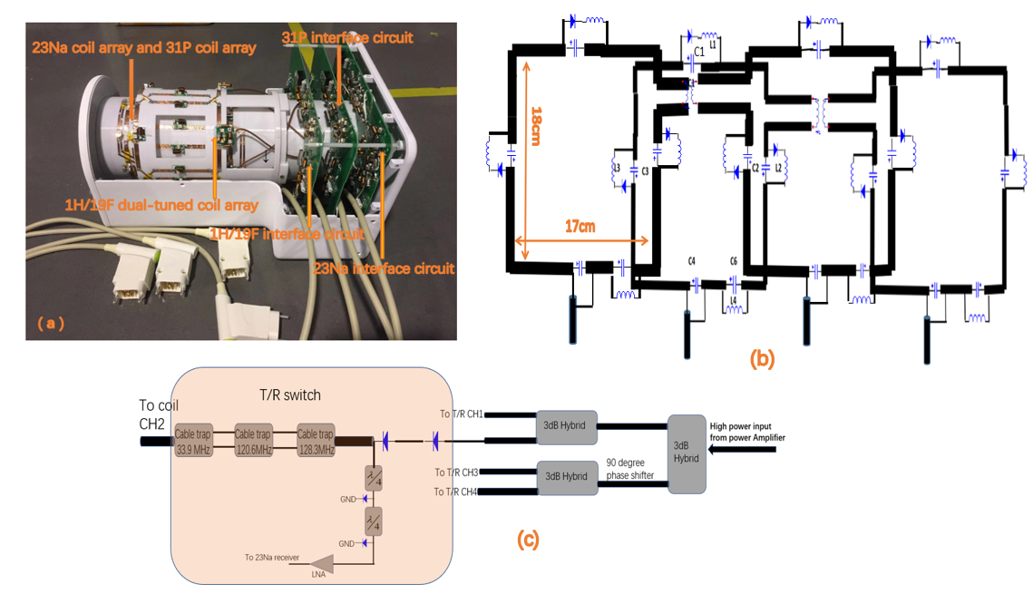
Two-layered concentric RF coil arrangement was built (Fig.1a). The inner 16cm-diameter cylindrical plastic tube was wrapped by two separate four-loop transceiver coils of 23Na and 31P (Fig.1b), while the outer 18cm-diameter tube wrapped by four dual-tuned loop coils that resonate at both 128.2MHz and 120.6MHz to allow simultaneous 1H and19F imaging(Fig.2a).To generate circularly polarized B1+ fields, all the transceiver arrays were driven through four output signals generated by their interface circuits with equal magnitude but 90 degree phase increments, corresponding to the azimuthal position of the coils. The interface circuit of 1H and 19F shared the same transceiver chain using a wide-band design, and was optimized at 124.4MHz, which can operate properly at 1H frequency (128.2MHz) and 19F frequency (120.6MHz) (Fig.2b). Two independent transceiver chains were built for 23Na and 31P, which were optimized at 33.9MHz and 51.9MHz, respectively (Fig.1c).
The elements of each mono-nuclear coil array were decoupled via geometric overlap and lumped element inductors (Fig.1b, Fig.2a). To reduce the parasitic parameter and the shielding effect caused by the 23Na array, the 1H/19F dual-tuned coil array was offset in the azimuthal direction by 45 degree . The 31P array was detuned when the 23Na array and the 1H/19F dual-tuned array were working simultaneously, and vice versa. To decouple the 31P and23Na/1H/19F arrays, three active detuning circuits were inserted in each loop of the arrays to reduce the residual interference and shielding effect caused by copper components from other array loops (Fig.1b, Fig.2a).
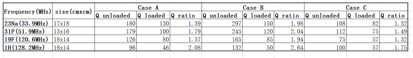
The coupling between arrays was examined by S21 measurement and the matching of transceiver loops was assessed by S11 measurement when loaded with a 12-cm-diameter cylindrical phantom. The Q factor and the Q ratio of the coil arrays were measured to assess coil performance. In particular, when 1H/19F/23Na coil arrays were working simultaneously, the impact of 23Na array on the 1H/19F loops was assessed by Q and Q ratio measurements with all the 23Na loops set on resonance.
Results and Discussion
The relevant amplitude and phase offset of four outputs generated by the interface circuit for all operating frequencies were well balanced with the absolute amplitude and phase offsets standard deviations were smaller than 0.2 dB and 6 degree, respectively (Fig.3). Therefore, after sending these outputs to drive the coil array of 1H/19F/23Na/31P with our properly designed azmuthmal positions, a homogeneous circular polarized B1+ field can be expected.All the coils were sufficiently matched, with the arithmetic maximum of reflection coefficient no larger than -17.1dB for all coil arrays (Table 1). A sufficient inter-element decoupling of the four coil arrays was also achieved with the isolation between any two loops no smaller than 14.8dB. When the 1H/19F/23Na arrays worked simultaneously while the 31P array was detuned, the minimum isolation between the 23Na array and the 1H/19F dual-tuned array was 33dB at 128.2MHz and 36.7dB at 120.6MHz.
To detune hetero-nuclear coil arrays, three active detuning circuits were used in each loop, which apparently reduced the Q ratio of each coil array, compared to the design where only one active detuning circuit was used (Table 2). The relatively low Q ratio of the transceiver loops in this design is a result of using added active detuning circuits which introduced additional loss. It indicated that our design should be further optimized to achieve a good trade off between decoupling and coil loss. When both the 1H/19F dual-tuned array and the 23Na array were on resonance while the 31P array was detuned, the average Q ratio slightly reduced, suggesting that the interference between coil elements through the cross-talk and coupling was well controlled.
Conclusion
In this study, a novel four-frequency 1H/19F/23Na/31P RF coil system was developed. Our performance evaluations showed that all coil arrays were sufficiently matched, decoupled and detuned when working simultaneously, and the unbalance of amplitude and phase increments generated by the interface circuits were well controlled, thus can be expected to generate a uniform B1+ field and high SNR images for simultaneous 1H/19F/23Na MRI and for 31P MRS. Future investigation will focus on phantom and animal study on a self-made 3T multinuclear MR system.Acknowledgements
This work was supported in part by NSFC under Grant No. 81627901References
1. Chang-Hoon Choi, Suk-Min Hong, et al. Design and construction of a novel 1H/19F double-tuned coil system using PIN-diode switches at 9.4T. Journal of Magnetic Resonance. 2017 April; 14(3): 279.
2. Dong-Ho Ha, Sunseob choi, Jong Young Oh, et al. Application of 31P MR Spectroscopy to the Brain Tumors. Korean J Radiol. 2013 May-Jun; 14(3): 477–486.3.
3. Madelin, G, Regatte, R. R, et al. Biomedical applications of sodium MRI in vivo . J. Magn. Reson. Imaging 2013;38:511–5294.
4.Franklin D.Hockett, Regatte, R. R, et al. Simultaneous Dual Frequency 1H and 19F Open Coil Imaging of Arthritic Rabbit Knee at 3T . IEEE Trans Med Imaging; . 2011 January ; 30(1): 22–27.
Figures