4094
Improving B1 fields and SNR for Proton MRI and MRSI at 7T using 4-piece Helmet filled with High Dielectric Constant (HDC) Material1CMRR, Department of Radiology, University of Minnesota, Minneapolis, MN, United States, 2CNMRR, Department of Neurosurgery, Penn State University, State College, PA, United States
Synopsis
Ultrahigh-field (UHF) MR systems allow non-invasive images with high sensitivity and spatiotemporal resolution. High dielectric constant (HDC) material utilized with RF coils has been shown to be promising for further improving RF transmitting power efficiency and increasing the signal-to-noise ratio (SNR) in previous studies. This work focuses on the application of a 4-piece HDC helmet-shaped former to different types of coils to demonstrate the consistency of improvement in B1 fields at 7T. The technology could enhance SNR and efficiency of RF transmission for brain 1H MR imaging application at UHF.
Introduction
The development of UHF MRI technology allows for the acquisition of high-resolution brain images providing insight into the structure and the functional network of the brain. However, the high magnetic field requires increased RF power transmission, which leads to higher energy absorption in the volume of interest and safety concern of operating high-field magnets. Previous studies with high-dielectric constant (HDC) material applied with RF coils have shown the improvement in the RF transmission and reception efficiency (B1 fields) at varied field strengths1-3. Due to the difference in robustness to the loading effect of HDC material on various types of coils, the verification of improvement in RF power transmission and detection sensitivity for different types of RF coils is necessary. Our goal is to test the consistent B1 improvement in different types of human head coils. A TEM head coil and a 16-channel loop transmit coil array with a single-channel receive coil were used in this study with a newly designed 4-piece slit HDC helmet at 7T.Methods
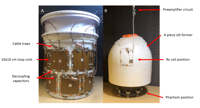
A 4-piece slit helmet-shaped former (coat thickness=1mm, gap thickness=8mm, material=PETG) was filled with HDC material (concentration=25% BaTiO3, relative permittivity εr=138). A TEM head volume coil, a 16-channel loop transmit array coil (Fig. 1A) with capacitive decoupling networks, and a single-channel receive coil were tuned at 298 MHz for 7T proton MRI and MRSI applications. A 2L-spherical water phantom containing 140mM sodium was used to test the TEM head coil, and a head-shaped phantom (concentration=65%PVP, 1.7% NaCl, 0.04% NiCl26H2O, 2% Agar) was used to collect data with the 16-channel loop transmit coil array and a single-channel receive coil. All phantoms were positioned at the center of coils for testing B1 improvements. CST studio suite software (Dassault Systèmes, France) was used to simulate the TEM head coil with the HDC former and the water phantom. AFI sequence was run to estimate the B1+ field in the 16-channel loop transmit coil array. The receive coil was placed on the surface of the former to test B1- improvement (Fig. 1B). FLASH sequence (TR=200ms, voxel size=2x2x5mm3) with varying RF transmit pulse voltages was operated on a Siemens 7.0T/90cm human scanner (Magnetom, Germany). B1+ estimation for the 16-channel loop transmit coil array was performed utilizing the method introduced by Van de Moortele et al4,5 and Metzger et al6. B1 fields for the TEM head coil and the single-channel receive coil were estimated by applying the relationship as described in the previous study7.Results
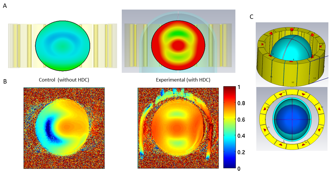
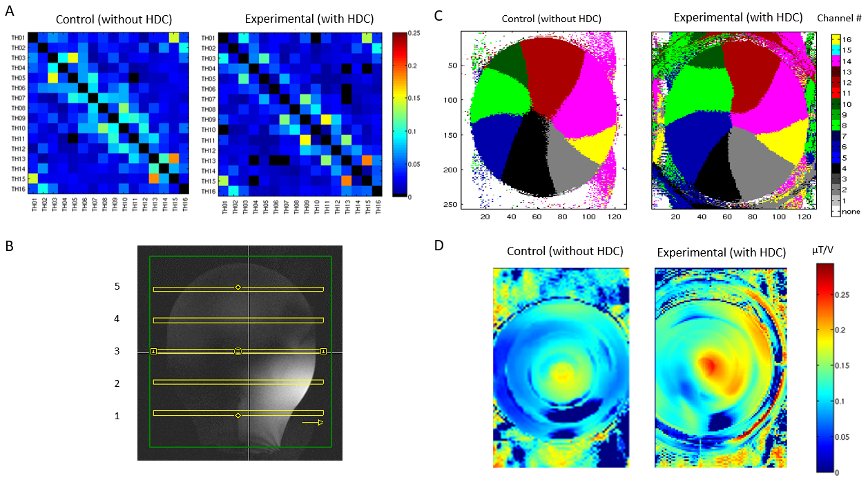
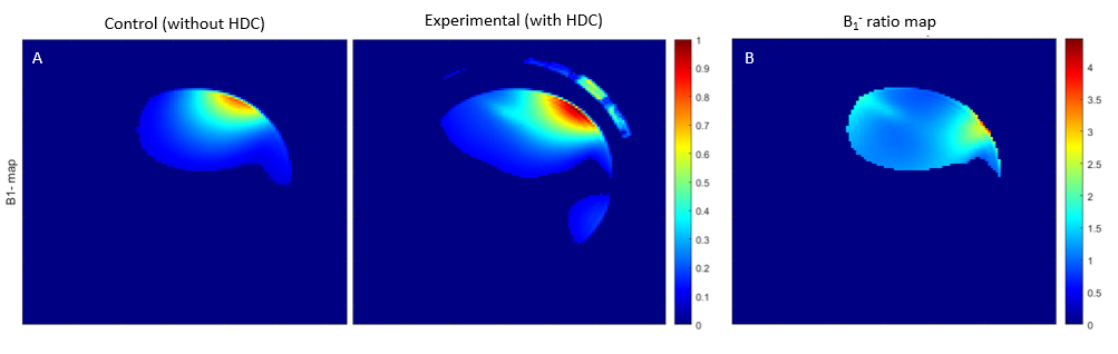
Fig. 2A shows the results of the simulation of the B1+ field for the TEM head coil with and without the use of the HDC helmet, and the B1+ field estimations for experimental data are shown in Fig. 2B. The B1+ fields of both simulation and experimental data show significant improvements for the TEM head coil with the HDC helmet. Fig. 3A shows a similar noise correlation among 16 transmit coils between with and without the HDC helmet inside the coil array, though indicating a slight reduction in the noise correlation with the HDC helmet. Fig. 3C presents the relative distribution of the RF field from multiple transmit coils at Slice 4 (Fig. 3B). The comparison of the B1+ fields of the 16-channel transmit coil with and without the HDC helmet is represented in Fig. 3D. The estimated B1‑ field of the single-channel receive coil is improved when HDC material is used near the coil (Fig. 4A). From the ratio of estimated B1- field (proportional to SNR) maps (Fig. 4B), the B1- field with HDC material has ~33% improvement compared to control.Discussion
The comparison of the results of both B1+ fields for the TEM head coil and the 16-channel loop transmit coil array showed significant improvements when HDC material was used, although B1+ fields were not uniform due to the wave interference at UHF. Additionally, the B1- field for a single-channel receive coil near the HDC former was significantly improved by ~33% from the coil without the HDC helmet. We found that it was robust to build receive coils on the helmet surface without notable interference. The penetration of the B1- field for the receive coil with the HDC material was deeper than control. This provides the possibility of imaging in a deeper volume of interest. Since a single-channel receive coil covered the local region near the coil, the multi-channel receive coil array would allow homogeneous images in deeper regions with whole-head imaging coverage and higher SNR than the coils without HDC material.Conclusion
In this study, we demonstrate that the application of the 4-piece HDC helmet-shaped former in different types of coils consistently showed the significant improvement of B1+ field efficiency RF transmission coils. Signal acquisition from a single-channel receive coil proved that B1- field was also significantly improved by applying the HDC helmet near the receive coil. This concept of a single-channel receive coil with the HDC helmet can lead to the demonstration of multi-channel receive coil array with HDC material to improve the sensitivity of RF coils in UHF MR applications, such as fMRI and in vivo MRSI for the human brain at 7T.Acknowledgements
This work was supported in part by NIH grants of U01 EB026978, R01 CA240953, R24 MH106049, T32 EB008389, S10 RR026783, P41 EB027061, P30 NS076408. R21 EB009133.References
1. Yang QX, Mao W, Wang J, Smith MB, Lei H, Zhang X, Ugurbil K, Chen W. Manipulation of image intensity distribution at 7.0 T: passive RF shimming and focusing with dielectric materials. Journal of magnetic resonance imaging : JMRI 2006;24(1):197-202.
2. Haines K, Smith NB, Webb AG. New high dielectric constant materials for tailoring the B1+ distribution at high magnetic fields. Journal of magnetic resonance 2010;203(2):323-327.
3. Yang QX, Wang J, Wang J, Collins CM, Wang C, Smith MB. Reducing SAR and enhancing cerebral signal-to-noise ratio with high permittivity padding at 3 T. Magn Reson Med 2011;65(2):358-362.
4. Van de Moortele PF, Urgurbil K. Very Fast Multi Channel B1 Calibration at High Field in the Small Flip Angle Regime. Proc Intl Soc Mag Reson Med 2009; 17: 367.
5. Van de Moortele PF, Akgun C, Adriany G, Moeller S, Ritter J, Collins CM, Smith MB, Vaughan JT, Urgurbil K. B1 destructive interferences and spatial phase patterns at 7T with a head transceiver arrray coil. Magn Reson Med 2005; 54 (6):1503-18.
6. Metzger GJ, Synder C, Akgun C, Vaughan T, Urgurbil K, Van de Moortele PF. Local B1+ shimming for prostate imaging with transceiver arrays at 7T based on subject-dependent transmit phase measurements. Magn Reson Med 2008; 59(2):396-409.
7. Lee BY, Zhu XH, Rupprecht S, Lanagan MT, Yang QX, Chen W. Large improvement of RF transmission efficiency and reception sensitivity for human in vivo 31P MRS imaging using ultrahigh dielectric constant materials at 7T. Magn Reson Imaging 2017;42:158-163.
Figures