4093
Passive RF shimming for 7T head coil with hybridized meta-atom: In vivo investigation1Institut Fresnel, Aix Marseille Université, CNRS, Marseille, France, 2CRMBM, Aix Marseille Université, CNRS, Marseille, France, 3CEA, DRF, JOLIOT, NeuroSpin, UNIRS, Gif sur Yvette, France, 4Multiwave Imaging, Marseille, France, 5ESPCI Paris, PSL Research University, CNRS, Institut Langevin, Paris, France
Synopsis
We show that hybridized meta-atom can be used to improve transmit homogeneity in a 7T head birdcage coil equipped with a 32-channel receive array. Our results demonstrates the enhancement of transmit signal in vivo with the possibility to fill one of the gap usually observed in the brain temporal lobes. This metamaterial based passive shimming strategy provides a cost effective, long-lasting solution without any impact on the patient’s comfort during the examination.
Background
Ultra-high field scanners benefits in terms of signal-to-Noise ratio (SNR) and Contrast-to-Noise ratio (CNR) are undermined by the inhomogeneous propagation of the radiofrequency (RF) field in the human body at 7T. Parallel transmission technique using multi-channels RF coils is being explored to solve this issue 1,2. Our aim is to tackle this hardware problem via passive RF shimming, i.e. inserting high dielectric constant materials 3,4,5 or metamaterial structures 6 around the subject to tailor the B1+ amplitude. We demonstrated in vitro that the hybridization of four parallel metallic wires arranged on a square unit cell provides the ability to control RF field inside a 7T head birdcage equipped with a receive array (1Tx/32Rx - Nova Medical, Wilmington, MA, USA) 7. Here, we show the first in vivo testing of the hybridized meta-atom (HMA) on two healthy volunteers with safe sequence protocols designed for RF prototype assessment at 7T 8.Methods
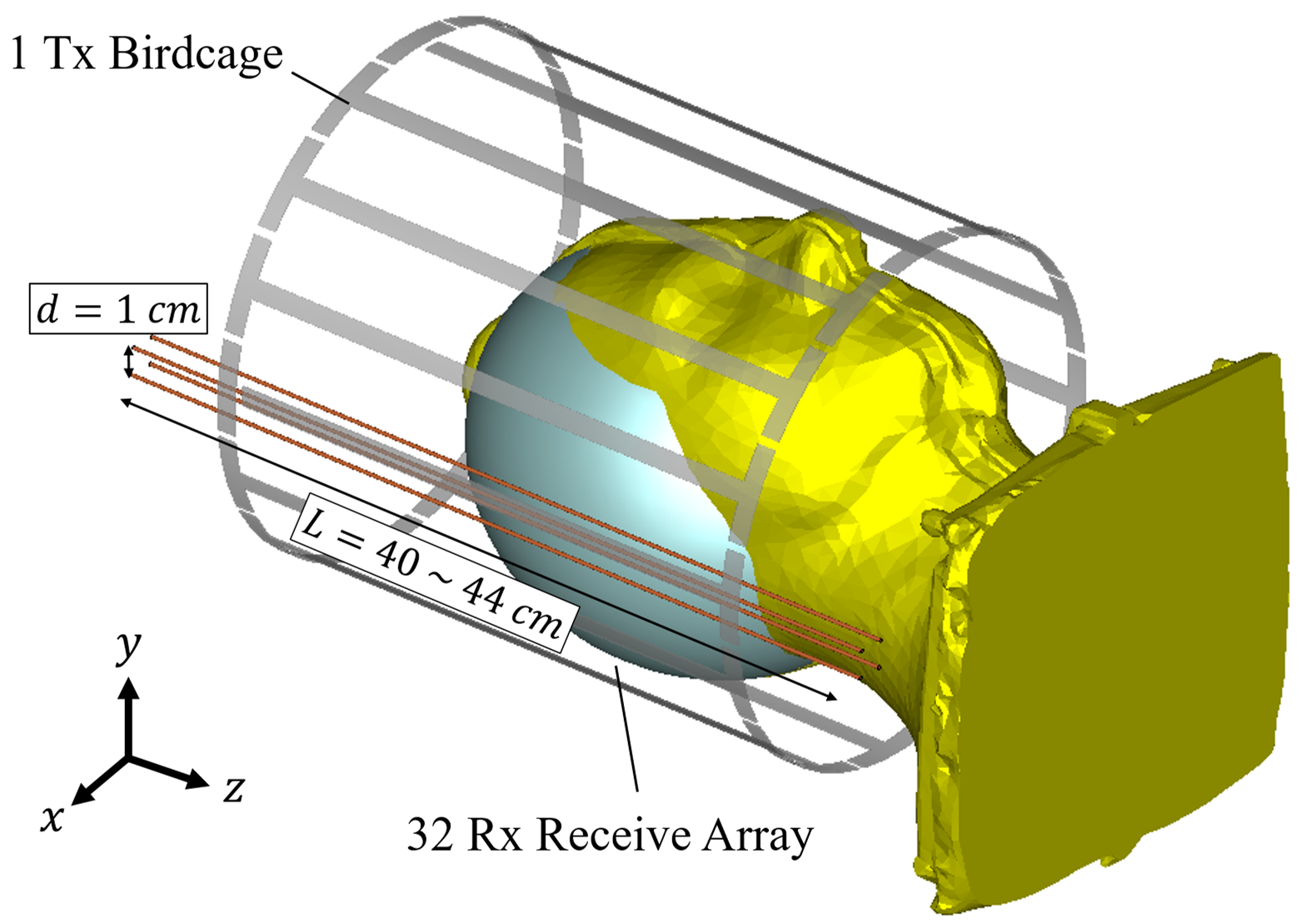
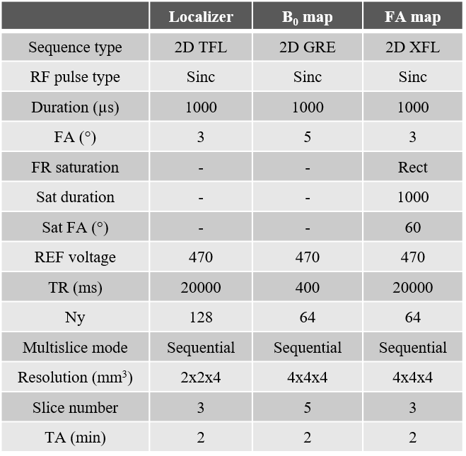
Four 1-mm-diameter brass wires are assembled at the four corners of a 1-cm-side square to form the HMA structure. The latter is then placed between the birdcage used for transmission and the receive array. Figure 1 presents a schematics of the experimental setup. MRI acquisitions were performed using a SC72 gradient dedicated 1Tx/32Rx proton head coil (Nova Medical, Wilmington, MA, USA) in a 7T Magnetom MRI scanner (Siemens Healthineers, Erlangen, Germany). Figure 2 presents the parameters of the in vivo protocol used. It includes a localizer (Proton density weighted), a B0 mapping and a flip angle (FA) mapping (XFL sequence 9). These parameters were enforced such that even if all the input power was focused and absorbed within 10g of tissues, the SAR would not exceed the regulatory limits (global and local SAR). The localizer and FA maps were acquired on three orthogonal slices sequentially. In vivo acquisitions have been done under local IRB rules on two healthy volunteers.Results
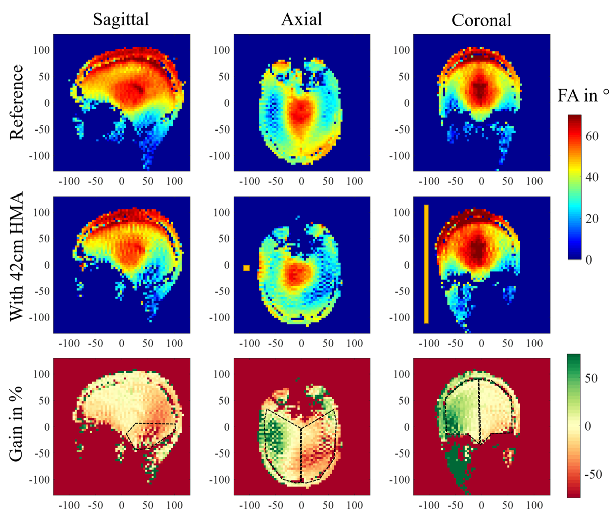
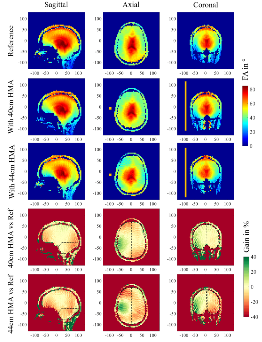
Results on the first volunteer are presented in Figure 3. It shows the FA map obtained for the reference scan without HMA in the three orientations (Vref 250V) and the same maps acquired when a 42-cm-long HMA is inserted (Vref 320V). The bottom row presents the relative gain between these two scans in percentage. Within the coronal slice, the right hemisphere of the brain indicates a 28% average gain in FA whereas the left one shows a reduction of 10%. The axial slice located at the eyes level exhibits an increase of +17% on the HMA side and a reduction of 27% on the opposite side. Meanwhile the loss in the cerebellum region is 34% on average. Figure 4 displays the results obtained on the second volunteer. The same methodology is applied, a reference scan was done first (Vref 250V), followed by two scans: one with a 40-cm-long HMA (Vref 275V) and another one with 44-cm-long HMA (Vref 325V) in the same location. Relative FA gain in percentage is presented in comparison with the reference FA map in each case. The relative gain in the coronal slice with 40-cm-long HMA is + 9% (similar for 44cm) on the HMA side and -2% (-9% for 44cm) on the opposite side. The loss in the cerebellum area is around 10% in each case. The effect in the axial slice is more localized than for the previous volunteer and the 40-cm-long HMA shows benefits on a larger brain volume.Discussion
The relative FA gain observed in Figure 3 is consistent with the observation made on specific anthropomorphic phantom 7. While the opposite side of the HMA shows some significant loss, the improvement on the HMA side is significant considering the poor FA distribution in the reference map, as usually encountered at 7T due to the volunteer’s head diameter. The second volunteer, displayed in Figure 4 presents a smaller head diameter which yields a more homogeneous FA distribution from the coil alone. In this case, we tested two different HMA lengths. First, we observe that the 40-cm-long HMA only increased the reference voltage by 10% which is positive regarding the transmit efficiency of the coil (FA with respect to the input power). Moreover, the size reduction (44cm to 40cm) does not affect strongly the performances of the HMA in terms of relative FA gain. The results indicate that a reduced length HMA should be a better solution but also show that the relative gain of the HMA depends on the head diameter as the load of the birdcage coil changes.Conclusion
The HMA solution previously studied in vitro was successfully tested on two volunteers. This technique features the ability to enhance locally the FA distribution together with the possibility to fill one of the gap usually observed in the brain temporal lobes. Future work will target the homogenization of FA in the whole brain with possibly the use of multiple elements of various dimensions. Finally, let us stress the benefits of the HMA is an ergonomic, cost effective, long-lasting solution without being in direct contact with the subject’s body. This last point is crucial for improving the patient’s comfort during examination.Acknowledgements
This work has received funding from the European Union Horizon 2020 Research and Innovation program under Grant Agreement No. 736937. It is also supported by the Leducq Foundation (large equipment ERPT program, NEUROVASC7T project).References
1 Katscher U. et al, NMR Biomed 2006; 19: 393–400
2 Grissom W. et al, Magn. Reson. Med. 2006; 56: 620–629
3 A. G. Webb, Concepts Magn. Reson. Part A 2011; 38A, 148
4 T. P. A. O’Reilly, A. G. Webb, and W. M. Brink, J. Magn. Reson. 2016; 270, 108-114
5 A. L. Neves, et al, Magn. Reson. Med. 2018; 79, 1753
6 M. Dubois, et al, Phys. Rev. X 2018; 8, 031083
7 M. Dubois, et al, Proc. Intl. Soc. Mag. Reson. Med. 2019; 27, 1491
8 A. Vignaud, et al, J. Phys.: Conf. Ser. 2018; 1092 012159
9 A. Amadon, et al, Proc. Intl. Soc. Mag. Reson. Med. 2015; 23, 2377
Figures