4092
Passive RF shimming with fractal metasurfaces in a 7T head coil1Aix Marseille Univ, CNRS, CRMBM, Marseille, France, 2Aix Marseille Univ, CNRS, Centrale Marseille, Institut Fresnel, Marseille, France, 3Multiwave Imaging, Marseille, France
Synopsis
B1+ inhomogeneities in the temporal lobes of the brain are common while using a birdcage coil at 7T. Different passive RF shimming approaches have already targeted this problem, at the cost of decreasing the B1+ field in other important areas or being uncomfortable to the patient. Here, we present a new approach based on two resonant fractal metasurfaces printed on ultra-thin flexible substrate. We show that these resonators improve the B1+ field amplitude simultaneously in each temporal lobe without affecting the B1+ field amplitude in other parts of the brain.
Introduction
Passive RF shimming approaches such as dielectric pads1-3 and metamaterials4,5 have been used to reduce the B1+ inhomogeneity observed in birdcage head coils working at 7T. While these approaches locally improve B1+ amplitude in regions of interest like temporal lobes, such improvements come at the cost of reducing the RF field in other ROIs like the cerebellum or being limited to use a single element. In this work, we present two passive RF shimming resonators for improving the B1+ field amplitude in each temporal lobe without diminishing the transmit efficiency of the birdcage coil elsewhere.Material and Methods
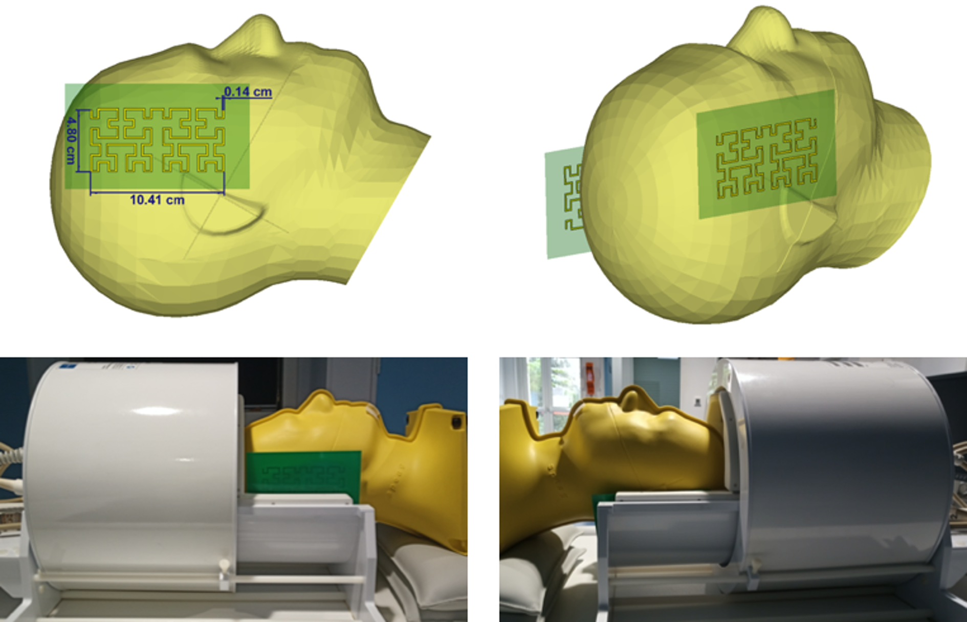
The resonant fractal metasurfaces are copper structures printed on a 0.4-mm-thick FR-4 substrate. The design of each resonant fractal was based on 4th-order Hilbert-fractal6 metallic strips as shown in Figure 1. Each fractal was placed on each side of the head, within the receive array. The fractal on the right side being slightly higher than the left one. The fractals were tested with a 1Tx/32Rx proton head coil (Nova Medical, Wilmington, MA, USA) in a 7T Magnetom MRI scanner (Siemens Healthineers, Erlangen, Germany) on a head specific anthropomorphic phantom (SPEAG, Zurich, Switzerland) filled with a liquid of permittivity ɛ= 45.3 and conductivity σ= 0.87 S/m.We measured Flip Angle (FA) and amplitude maps using the XFL MRI sequence7 in sagittal and axial orientation with TR= 20 s, TE= 1.4 ms, FA= 8°, Shinnar-Leroux minimum-phase saturation pulse= 90°, FOV= 256 mm, matrix= 64x64 and 12 slices of thickness= 8 mm (17 slices in axial orientation). A mask extracted from GRE images was applied to the FA maps. The relative FA and amplitude signal gain expressed in percentage were computed for a quantitative analysis of the fractals effect. All images were acquired using the same reference voltage of 260V.
Results
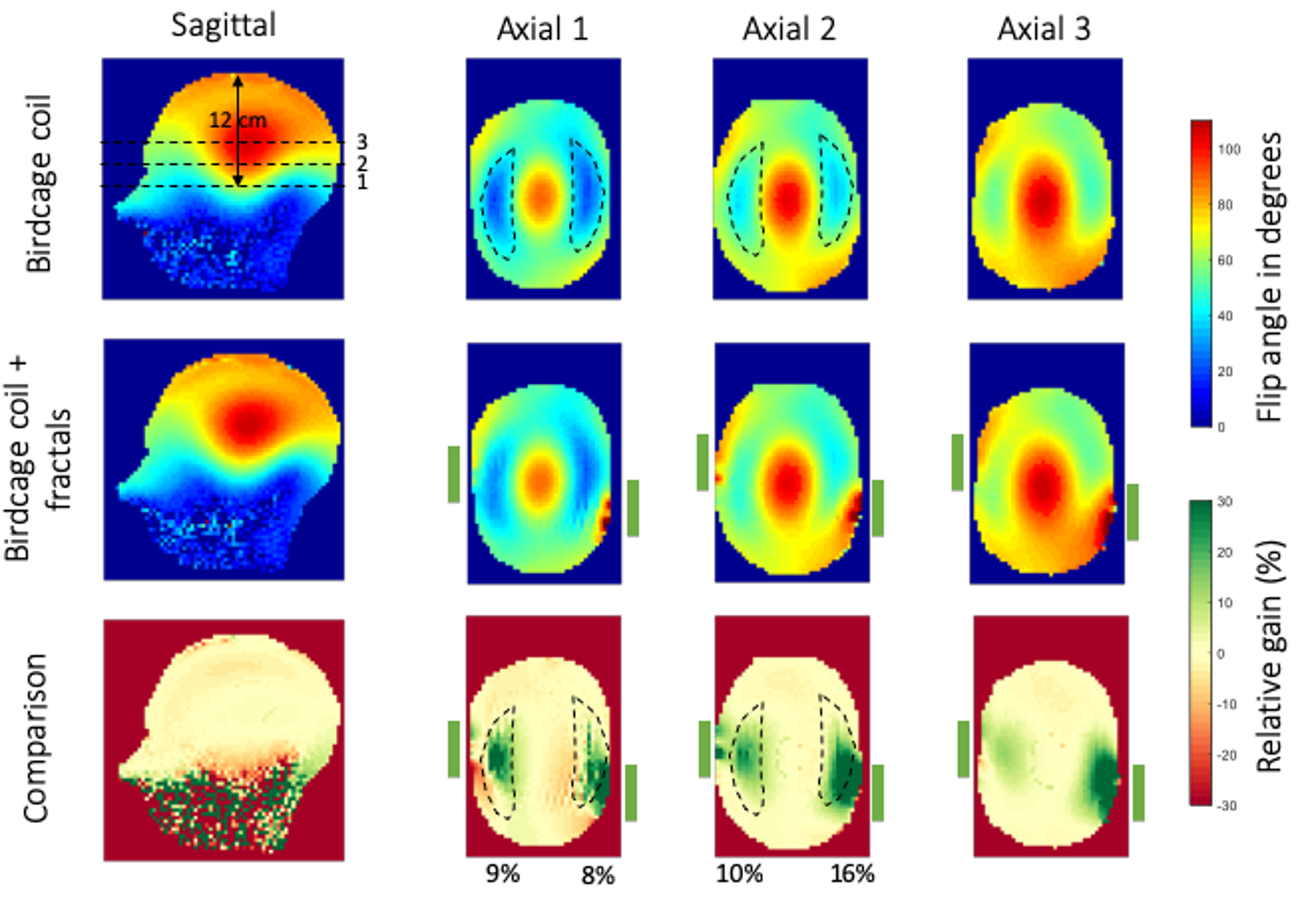
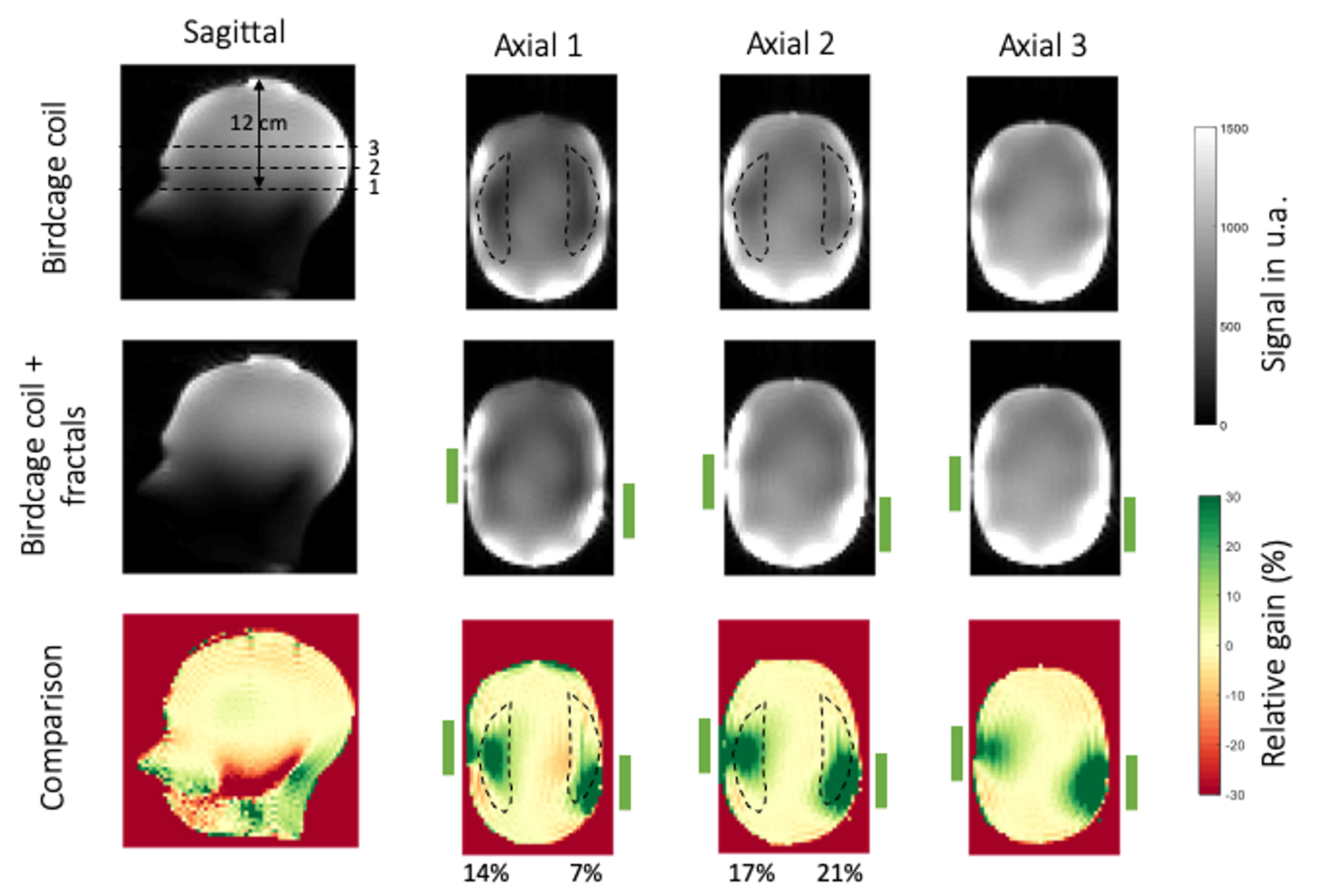
FA maps in sagittal and axial orientations of the birdcage coil alone (top row), and with the fractals (central row) are shown in Figure 2. The effect of the fractals can be seen at different locations in the head through the three axial slices denoted with dashed lines. The first one is located at 12 cm from the top of the head. The space between the two axial slices is 24 mm. Relative FA gain maps are shown in Figure 2 bottom row. The green rectangles next to the axial slices represent schematically the position of the fractals with respect to the phantom. We can see a significant increase of the FA while using the fractal. It corresponds to a 30% gain around the area were the fractals were placed and 10% on average in the ROIs that denote the temporal lobe regions. Moreover, from the sagittal slice, no loss is observed in other regions of the brain such as the cerebellum.Figure 3 presents GRE signal maps (unprocessed data from the XFL sequence) of the birdcage coil alone (top row) and with the fractals (central row). All GRE images were acquired with an input power of 260V. Similarly, the last row of Figure 3 shows the relative gain between the fractals over the reference signal. We can see that the 30% enhancement obtained in the FA maps is reflected on the GRE images while the average gain in the ROIs seems to increase slightly and low loss is observed in the remaining brain region.
Discussion
We based the design of the metasurface pads on a Hilbert-fractal with the aim to obtain compact, thin and flexible resonant structures. Due to their complex design, the fractals are quite sensitive to the location and orientation with respect to the birdcage coil. The optimized positions were found to respect the original asymmetry of the B1+ field amplitude in the reference FA maps. The presence of the fractals shows a maximum +30% gain of B1+ amplitude for both temporal lobes, for the same input voltage which is interpreted as a large increase in transmit efficiency (Figure 2). Moreover, they maintain the B1+ amplitude almost intact in the remaining brain volume. This effect is particularly interesting for the cerebellum region which usually suffers when high dielectric constant pads or metamaterials are inserted in the birdcage coil. In our case, most of the loss seems to be directed towards the lower part of the head away from the brain ROI where the birdcage coil stops. This can be seen in the sagittal slices in Figures 2 and 3. Moreover, as the relative gain observed in the FA maps in Figure 2 is conserved and slightly improved in the GRE images, it indicates that the fractals do not interfere with the receive array.Conclusion
We designed metasurface pads inspired by a Hilbert-fractal design to reduce the transmit field inhomogeneity artefacts observed in head imaging with high-field MRI. We found that the resonant fractal metasurfaces improve the B1+ amplitude up to a maximum 30% and 10% on average in the two temporal lobes without compromising the B1+ amplitude in the cerebellum. Their compact and flexible design allows them to fit easily between the phantom and the receive array of the head coil. Hence our approach promises better performance and patient comfort over conventional dielectric pads or metamaterials.Acknowledgements
This work has received funding from the European Union Horizon 2020 Research and Innovation program under Grant Agreement No. 736937.References
[1] Webb A. G., Concepts Magn. Reson. Part A 38A (2011), 148
[2] O’Reilly T. P. A., et al., J. Magn. Reson. 270 (2016), 108-114
[3] Neves A. L., et al., Magn. Reson. Med. 79 (2018), 1753
[4] M. Dubois, et al., Phys. Rev. X 8 (2018), 031083
[5] M. Dubois, et al., Proc. Intl. Soc. Mag. Reson. Med. 27 (2019) 1552
[6] Hilbert D., Mat. Ann., Springer, 38 (1935), 459-460
[7] Amadon A., et al., Proc. Intl. Soc. Mag. Reson. Med., 23 (2015) 2377
Figures