4091
NEAR-FIELD ELECTROMAGNETIC CLOAKING OF METALLIC ELONGATED IMPLANTS TO REDUCE RF-INHOMOGENEITY ARTIFACTS AND SAR ELEVATION
Umberto Zanovello1 and Luca Zilberti1
1Istituto Nazionale di Ricerca Metrologica (INRIM), Torino, Italy
1Istituto Nazionale di Ricerca Metrologica (INRIM), Torino, Italy
Synopsis
The eddy currents induced by the RF magnetic field B1 due to the presence of a conductive object, such as a metallic implant, may compromise both the RF coil transmit and receive sensitivity homogeneity; especially in the periprosthetic areas. A further effect may be an increase of the local SAR which can affect the overall safety of the MRI exam. In this study, the outcomes of an electromagnetic cloaking strategy based on the application of a suitable coating to elongated conductive implants are shown. The coating restores the coil sensitivities and SAR distribution to those obtained without the implant presence.
INTRODUCTION
The presence of metallic passive implants in a patient submitted to an MRI scan may compromise both the quality of the MR image and the safety of the exam itself. The interaction between the metallic object and the static magnetic field B0 has been recognised to be one of the most important cause for metal-induced artifacts1,2. However, several artifacts mitigation sequences and techniques3 (e.g. SEMAC, MAVRIC, Filtered Back-Projection methods etc.) have been studied to address the problem and some of them are already implemented in today commercial scanners. Another source of artifacts may be given by the eddy currents induced by the RF magnetic field B1 due to the conductive object presence4. These currents generate a scattered magnetic field which can affect both the transmit sensitivity (B1+) and the receive sensitivity (B1-) homogeneity in the periprosthetic areas. To the best of the authors’ knowledge, only two possible strategies can be adopted today to reduce such an issue: adiabatic pulses5 and multichannel transmission6. Whereas the former are generally more difficult to be designed and implemented with respect to standard RF pulses and only improve the transmit sensitivity, the latter requires a preliminary optimization, based on the specific implant position inside the RF coil, to identify the proper field polarization. A further possible effect of the interaction between a conductive implant and the RF field is represented by an increase of the local SAR which can affect the overall safety of the MRI exam7. Whereas, even in this case, multichannel transmission demonstrated beneficial effects8, it still requires the preliminary study aimed to identify the optimum field polarization. This work shows, by means of numerical simulations, the effects of a near-field electromagnetic cloaking aimed to restore the magnetic and electric field (and, therefore, SAR) distributions to those obtained without the detrimental effects of the implant9,10.METHODS
The electromagnetic interaction between a generic birdcage coil and an elongated metallic object placed inside a tissue-mimicking phantom has been approximately described by means of a lumped element equivalent circuit (Fig. 1). The capability of such a circuit to properly describe the occurring phenomena has been tested by comparing the expectations from the circuit to the results obtained through full-wave simulations. With the aid of the equivalent circuit, a strategy has been identified to reduce the effects of the conductive implant presence, namely to cover the object with a non-conductive dielectric coating with suitable relative electric permittivity and thickness. A preliminary analysis, aimed to identify the possible relation between a proper coating permittivity and thickness, has been performed at 128 MHz considering a metallic cylinder. Thereafter, the study has been extended to 64 MHz and to a realistic model of a hip prosthesis stem. Both the B1+ magnitude homogeneity, evaluated over different slices by means of the its standard deviation, the B1+ phase and the SAR distribution have been taken into account to estimate the cloaking effectiveness.RESULTS
As regards the investigated range of coating thickness values (≤ 10 mm), the effectiveness of the dielectric coating is influenced by the ratio between its thickness and electric permittivity. The proper ratio between such parameters strongly depends on the B1 frequency, being lower at higher frequency values. This results, at 128 MHz, in a suitable coating relative permittivity lower than one, requiring to design a proper metamaterial in order to realize the coating itself. The situation turned out to be different focusing on a frequency equal to 64 MHz, where the coating relative permittivity can be higher than one even considering a thin (2 mm) coating thickness. Figures 2 and 3 depict the magnitude and phase of the transmit sensitivity in a coronal slice, whereas figure 4 shows the SAR distribution over the same slice. For the sake of comparison, the empty phantom scenario is reported, together with those relevant to the uncoated and coated prosthesis. As regards the coated implant, a 2 mm Teflon® coating has been applied.DISCUSSION
The application of the 2 mm Teflon® coating restores the original homogeneity of the B1+, leading to standard deviations comparable to those obtained with the empty phantom. Analogous beneficial effects are appreciable focusing on the B1+ phase, where the coating application strongly reduces the phase incoherencies in the periprosthetic areas. Finally, the local SAR peaks, recorded when the uncoated prosthesis is placed inside the phantom, are noticeably decreased after the implant has been covered with the coating.CONCLUSION
Results highlight the beneficial outcomes obtained covering an elongated implant, such as a hip prosthesis, with a non-conductive dielectric coating with suitable thickness and electric permittivity. Positive effects are observed both for B1+ and for SAR at 64 MHz employing a 2 mm coating made of an existing material such as Teflon®. Differently, a dielectric coating with a comparable thickness should have a relative permittivity lower than one at 128 MHz. In the last case, it should be realized by means of a properly designed metamaterial.Acknowledgements
No acknowledgement found.References
- Hargreaves, B. A. et al. Metal-Induced Artifacts in MRI. Am J Roentgenol.2011;197:547-555.
- Schenck, J. F. The role of magnetic susceptibility in magnetic resonance imaging: MRI magnetic compatibility of the first and second kinds. Med Phys.1996;23:815-850.
- Koch, K. M. et al. Magnetic Resonance Imaging Near Metal Implants. J Magn Reson Im.2010;32:773-787.
- Camacho C. R., Plewes, D. B. & Henkelman, R. M. Nonsusceptibility Artifacts Due to Metallic Objects in Mr-Imaging. J Magn Reson Im.1995;5:75-88.
- Tannus A., Garwood M. Adiabatic pulses. NMR in Biomed.1997;10:423-434.
- T.J. Bachschmidt et al. Polarized multichannel transmit MRI to reduce shading near metal implants. In: Magnetic Resonance in Medicine.2016;75(1):217-226.
- Henry, S. Ho. Safety of metallic implants in magnetic resonance imaging. J Magn Reson Im.2001;14:472-477.
- Nadja, A. 3-T MRI implant safety: heat induction with new dual-channel radiofrequency transmission technology. European Radiology Experimental.2018;2:7.
- Zanovello, U. et al. An ideal dielectric coat to avoid prosthesis RF-artefacts in Magnetic Resonance Imaging. Sci Rep.2017;7:326.
- Zanovello, U. et al. A Near Field Cloaking Study to Reduce MRI RF-Artefacts in Presence of elongated Prostheses. IEEE Journal of Electromagnetics, RF and Microwaves in Medicine and Biology.2018.
Figures
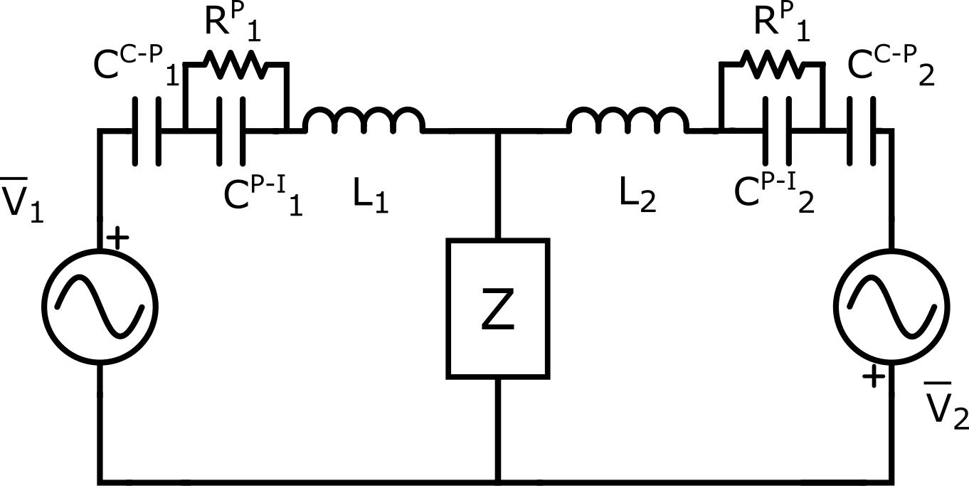
Figure 1: Lumped element circuit describing the interaction with the RF
coil and a conductive elongated implant. V1,2 are induced voltages,
CC-P1,2 are the coil-phantom capacitances, CP-I1,2
are the phantom implant capacitances, L1,2 are inductive
reactions and Z takes into account the presence of the conductive implant.
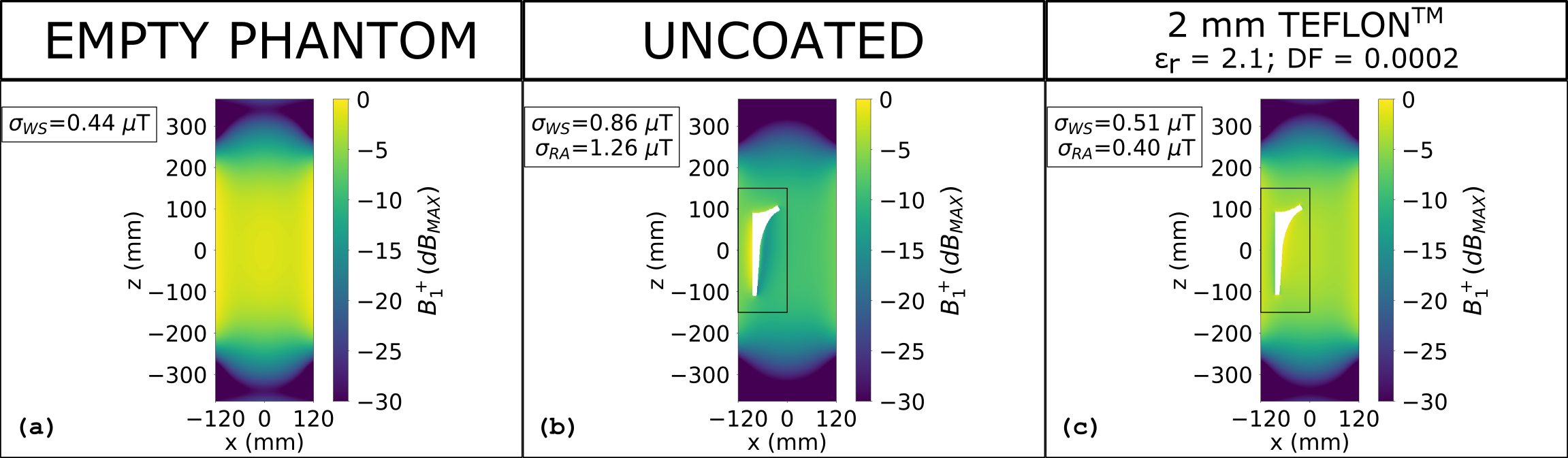
Figure 2: Magnitude of B1+ expressed in dB with
respect to its maximum value over the slice and evaluated at 64 MHz for the
empty phantom (a), the laterally placed uncoated and coated prosthesis (b,c).
The rectangles represent the reduced areas in which the standard deviation (𝜎𝑅𝐴)
of the B1+ magnitude is computed. 𝜎𝑊𝑆
represents the standard deviation computed on the whole slice.
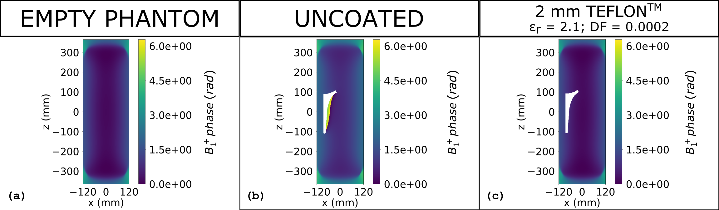
Figure 3: B1+
phase evaluated at 64 MHz for the empty phantom (a), the laterally placed uncoated
and coated prosthesis (b,c).
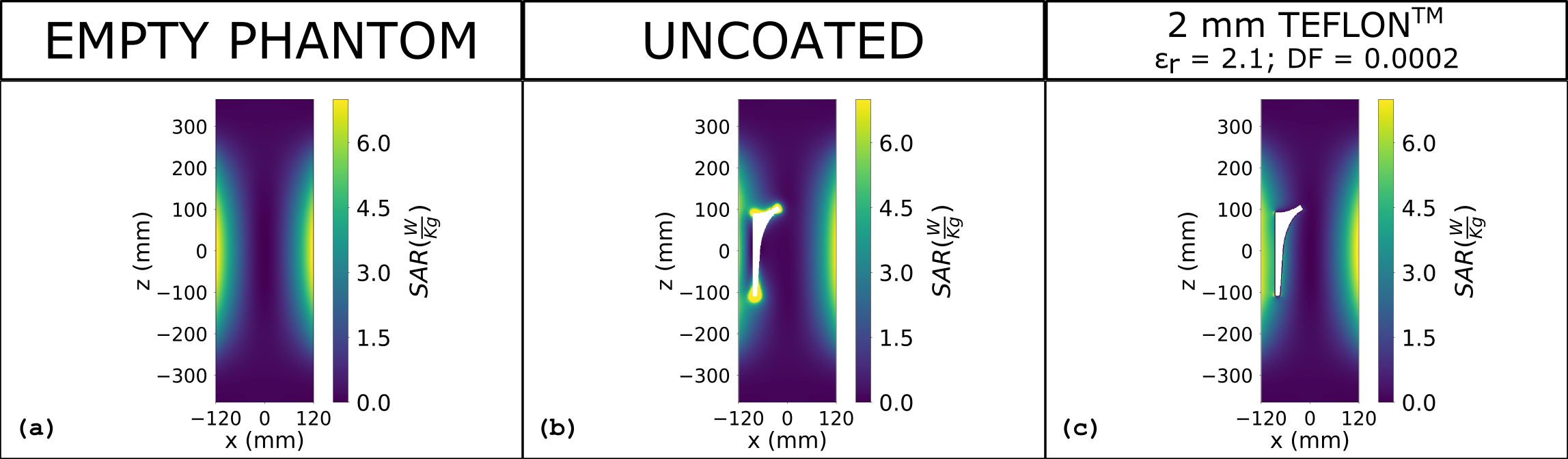
Figure 4: SAR
distribution evaluated at 64 MHz for the empty phantom (a), the laterally
placed uncoated and coated prosthesis (b,c). The SAR has been normalized to a
volume average SAR inside the phantom equal to 2 W/kg.