4088
Distribution and Propagation of Fields and Displacement Currents in a high-permittivity helmet
Giuseppe Carluccio1,2, Qing X Yang3, and Christopher Michael Collins1,2
1Radiology, Center for Advanced Imaging Innovation and Research (CAI2R), New York, NY, United States, 2Radiology, Bernard and Irene Schwartz Center for Biomedical Imaging, New York, NY, United States, 3Radiology, Penn State University, Hershey, PA, United States
1Radiology, Center for Advanced Imaging Innovation and Research (CAI2R), New York, NY, United States, 2Radiology, Bernard and Irene Schwartz Center for Biomedical Imaging, New York, NY, United States, 3Radiology, Penn State University, Hershey, PA, United States
Synopsis
High-permittivity material (HPM) helmets have provided significant increase in transmit efficiency and local SNR. However, the physical mechanisms that explain such improvements are still not fully explored. In this work, through electromagnetic simulations, we analyze the fields propagation when a loop is placed near the occipital lobe with and without the presence of an HPM helmet. The analysis is performed observing the field propagation through time, the direction and the amplitude of the Poynting vector, and the current density distribution.
Introduction
There is a growing interest for the use of High-permittivity materials (HPM) in MRI applications. The use of HPM have shown very promising results in terms of SNR increase, B1 field homogeneity, and higher transmit efficiency. For example, a recently designed HPM helmet former, when used in combination with a 28 channels receive array, in simulations could provide a significant SNR increase over the whole brain (about 50%) compared to when the same coil array is used without the HPM helmet1.The optimum value of permittivity and the shape of the HPM depends on many parameters including the operating frequency of the scanner and the thickness of the HPM. For example, three different optimum values of permittivity for coil designs at three different field strengths were found for HPM helmet formers2. Although a mathematical relationship between the optimum permittivity and the operating frequency has been postulated2, the physical mechanisms that describe the impact of the HPM on the fields distribution are still not completely explored. In this work, we investigate how the HPM materials in a helmet shape the electromagnetic field distributions and help to increase SNR in the head. Since it is not easy to understand the physical mechanisms by examining the electromagnetic fields when all the loops of the receive array are active, we will focus our analysis on the impact of the HPM on the field distribution of a single loop of the array.
Methods
The electromagnetic field distributions of a loop coil positioned on the back of the head is analyzed through electromagnetic simulations (Fig. 1). The fields were computed at 300 MHz, corresponding to the Larmor frequency of the 7T scanners, with the commercial software xFDTD (Remcom, inc.; State College, PA USA). A subsequent analysis of the fields was performed with Matlab (the Mathworks, Natick, MA; USA) scripts. The human body model used for the simulations was “Duke” of the virtual family3, and the permittivity and conductivity values of the tissues were set according to the operating frequency.In total, two electromagnetic simulations were performed: the fields were computed for the helmet permittivity equal to 1 (corresponding to the case of no helmet) and 115. For both cases, the electrical conductivity of the helmet was set to 0.
For the transverse slice located at the center of the coil, the propagation of electric and magnetic field amplitudes are shown through an animated GIF image for all the considered cases in Fig. 2. For the same slice, the Poynting vector S was computed:
$$S =\frac{1}{2} E \times H*$$
and current density in each direction were computed as the sum of the conductive current and displacement currents:
$$J = \sigma E+ \epsilon \frac{\partial E}{\partial t}$$
Results and Discussion
The distribution of the amplitude and of the direction of the Poynting vector is shown in Fig. 3 for the simulated cases. Fig. 4 shows the relative SNR for three different orthogonal views. The sum of the conduction and of the displacement current is shown on a transverse plane in Fig. 5.As can be observed in Fig. 2, without the helmet the fields seem to propagate directly into the head. On the contrary, when the helmet is present, the fields seem to propagate first along the helmet around the head. This is confirmed by the direction and the amplitude of the Poynting vector reported in Fig. 3. Therefore, the helmet seems to act somewhat as a waveguide that facilitates propagation of the fields around the head. This is confirmed by the SNR distributions in Fig. 4. In fact, in cases of no helmet the fields are more concentrated near the coil and therefore, in those locations, the presence of the helmet decreases SNR. On the contrary, for all the other locations, the SNR is significantly higher when the helmet is used.
Also the high displacement current in the helmet shown in Fig. 5 indicates that the current is distributed more uniformly through space, including in the helmet, and not only in the coil. This provides a more homogeneous excitation in the head, and not only localized as in the case without the helmet.
While the SNR from a single coil may be lower near the coil in the presence of the HPM, when all coils in an array have higher SNR far from the coil, the net effect is higher SNR throughout the region of interest1.
Conclusion
The HPM helmet tends to redistribute the fields all around the head, and it provides a weaker decay of the fields in the locations of the head far from the coil. When multiple coils are used like in a receive array, overall SNR benefits from the presence of the helmet because in each location the signal from all the coils except the nearest is stronger when the helmet is present.Acknowledgements
This work was supported by National Institutes of Health grant R01EB021277 and was performed under the rubric of the Center for Advanced Imaging Innovation and Research (CAI2R, www.cai2r.net) at the New York University School of Medicine, which is an NIBIB Biomedical Technology Resource Center (NIH P41 EB017183).References
- G. Carluccio, G. Haemer, C. M. Collins, “SNR improvement when a High Permittivity Material helmet-shaped former is used with a close-fitting Head Array”, In 2018 International Conference on Electromagnetics in Advanced Applications (ICEAA), 2018 Sep 10 (pp. 304-306). IEEE.
- C. M. Collins, G. Carluccio, B. Zhang, G. Adriany, K. Ugurbil, R. Lattanzi, “On the Relationship Between Field Strength and Permittivity for Desired Effects of High-Permittivity Materials in MRI” in ISMRM 27th annual meeting and exhibition 11-16 May 2019, 1566.
- A. Christ, W. Kainz, E. G. Hahn, K. Honegger, M. Zefferer, E. Neufeld, W. Rascher, R. Janka, W. Bautz, J. Chen, B. Kiefer, “The virtual family—development of surface-based anatomical models of two adults and two children for dosimetric simulations”. Physics in Medicine & Biology, 2010;55: N23–N38.
Figures
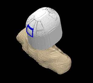
Figure 1: Geometry of the problem
Figure 2: time evolution of the propagation of the component vectors of the electromagnetic fields when no helmet is present (top rows) and when the HPM helmet is used (bottom rows).
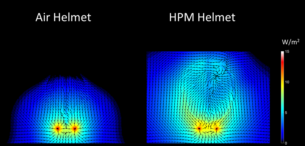
Figure 3: Plot of the Poynting vector amplitude (color distribution, logarithmic values) and direction (arrows) without the helmet (left) and with the helmet (right).
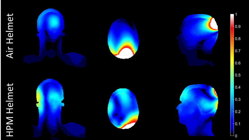
Figure 4: plot of the relative SNR for three orthogonal views for the case when no helmet is present (top) and when the HPM helmet is used (bottom).
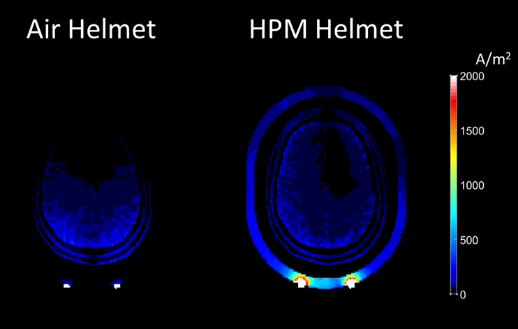
Figure 5: plot of the sum of the conductive current density and of the displacement current density, when no helmet is used (left) and when the HPM is used (right).