4087
Dielectrically-Shortened Dipole Antennas for MRI at 7.0 T: Thick or Thin?
Daniel Wenz1 and Rolf Gruetter1,2,3,4
1Center for Biomedical Imaging - Animal Imaging and Technology (CIBM-AIT), Ecole Polytechnique Fédérale de Lausanne (EPFL), Lausanne, Switzerland, 2Laboratory of Functional and Metabolic Imaging (LIFMET), Ecole Polytechnique Fédérale de Lausanne (EPFL), Lausanne, Switzerland, 3Department of Radiology, University of Lausanne, Lausanne, Switzerland, 4Department of Radiology, University of Geneva, Geneva, Switzerland
1Center for Biomedical Imaging - Animal Imaging and Technology (CIBM-AIT), Ecole Polytechnique Fédérale de Lausanne (EPFL), Lausanne, Switzerland, 2Laboratory of Functional and Metabolic Imaging (LIFMET), Ecole Polytechnique Fédérale de Lausanne (EPFL), Lausanne, Switzerland, 3Department of Radiology, University of Lausanne, Lausanne, Switzerland, 4Department of Radiology, University of Geneva, Geneva, Switzerland
Synopsis
Shortening dipole antennas using dielectric materials provides an opportunity to design very high-channel count dipole arrays which should boost signal-to-noise ratio and enable higher acceleration factors in parallel MRI at 7.0 Tesla. In this study, we compare different dipole antennas shortened using D2O. We demonstrate, that the height of the dielectric block becomes a critical design parameter when there is no direct contact between the block and the sample and what we know about dielectric block design should be revisited. Our results indicate, that miniaturizing dipole antennas, and employing them in an 8-channel configuration, is feasible without significant performance decrease.
Introduction
Dipole antennas (DA) are inevitable to achieve the ultimate intrinsic signal-to-noise ratio (UISNR) in ultrahigh field (UHF) MRI1. DA arrays, which are built of high number of channels, can provide higher acceleration factors in parallel MRI and higher SNR2,3,4,5. For this purpose, the DA geometry requires some modifications. One of the approaches is to shorten DA using high-dielectric constant εr medium6,7,8. Unfortunately, the sizes of dielectric blocks (DB) used in previous investigations were rather large. Those reports have followed what Raaijmakers et al. have suggested in their landmark paper6, i.e. that the height of DB should be bigger than ¼ of λ. This condition seems to be true when there is direct contact between DB and the sample. However, when DB has a higher dielectric constant εr (e.g. 80), and a small, 5-mm air gap is present between DB and the sample, the electromagnetic field (EMF) pattern changes substantially and there is no efficient RF power delivery to the sample. In this study, we investigate transmit field (B1+) produced by four different DA designs immersed in heavy water (D2O) by conducting EMF simulations and MR phantom experiments. We also compare in simulations three types of DA arrays including one that is comprised of a miniaturized version of one of the elements.Methods
Electromagnetic field (EMF) and specific absorption rate (SAR) simulations were performed in spherical (diameter=85mm) and cubic phantom (size=300x300x200mm3), conductivity σ=0.4 S/m, dielectric permittivity εr=80) using Sim4Life (ZMT AG, Switzerland). Three different single elements were investigated: RA-S, B-T7, SSAD8. DB dimensions were: RA-S (97.5x47.6x28.6mm3), B-T (155x70x25mm3), SSAD (160x70x50mm3). RA-S geometry was scaled from 6 according to the higher εr (80 instead of 36). The elements were built of acrylic glass boxes filled with D2O. Since our goal at this stage was a qualitative comparison, acrylic glass was not included in our simulations. Phantom experiments were conducted on a 7.0 Tesla head-only system (Magnetom, Siemens Healthineers, Erlangen, Germany) and phantom images, which are related to transmit field, were obtained using SA2RAGE imaging technique9. The geometry of miniaturized B-T (B-T-m) was arbitrarily modified: 105x60x5mm3. RA-S, SSAD, B-T and B-T-m were used in 8-channel DA arrays that were driven in a circularly polarized (CP) mode (phase increment/element=45°).Results
Figure 1 shows that B1+ distribution in cubic and spherical phantom is substantially different between setup A (direct contact, no air gap) and B (5-mm air gap). In setup B, the magnetic field does not propagate down towards the sample and is contained within DB. As a result, a dramatic decrease in B1+ (B1+/√Pin) and SAR (B1+/√SAR10g) efficiency is observed (Figure 1 and 2). Phantom measurements are in rough agreement with simulations (experimental conditions were slightly different). The observed effect is associated with the height of DB. The resulting EM field was also related to the phantom's geometry. Only element B-T (shortest distance between the antenna feed and the bottom of DB) performs well despite the air gap. In setup A, B1+ efficiency is not proportional to the DB height, but rather finds its optimum around 12.5 cm (Figure 3). However, even higher DB (height=22.5cm) can produce efficient B1+. Scattering parameter matrix (Figure 4) was analyzed for setup A and B (DB height=20cm). It indicates that such high DB has at least several dielectric modes in setup B. Miniaturized version of B-T in an 8-channel configuration, provides higher B1+ efficiency in superficial region and only 3% lower B1+ efficiency in the center of the phantom than 8-channel B-T array.Discussion and Conclusion
We showed, that performance of DA, which are shortened using too high DB, can be completely degraded when a small air gap is present between DB and the phantom. This effect disappears when the distance between the feed of DA and the bottom of DB is reduced. Our observations disagree with what was reported previously, i.e. that the height should be at least ¼ λ. This condition remains true when there is direct contact between the block and the sample. Direct contact between DB and the sample leads to smooth EM wave propagation, and an optimal DB height to maximize B1+ efficiency at given depth can be found. This is not the case when there is a sufficiently small air gap between DB and the phantom. We conclude that this effect can be related to a coupled dielectric mode of DB. This hypothesis is yet to be fully confirmed in future experiments. Our work has important implications for DA design using dielectric materials especially for brain UHF-MRI. It is rarely the case that direct contact between DB and volunteer's head can be achieved. We also extended our work, and showed in simulations, that significant reductions in overall size of DB are possible without substantial B1+ efficiency decrease in 8-channel array configuration. This is very promising for high-channel count, receive-only dipole or loop/dipole arrays. There is a broad range of available, low loss dielectric materials with higher εr which could be considered in future DB design optimizations, and their potential benefits for UHF-MRI should be investigated.Acknowledgements
No acknowledgement found.References
1. Lattanzi R, et al., Approaching ultimate intrinsic signal-to-noise ratio with loop and dipole antennas. Magn Reson Med. 2018 Mar;79(3):1789-1803. 2. Roemer PB, et al., The NMR phased array. Magn Reson Med. 1990 Nov;16(2):192-225. 3. Sodickson DK, Manning WJ, Simultaneous acquisition of spatial harmonics (SMASH): fast imaging with radiofrequency coil arrays. Magn Reson Med. 1997 Oct;38(4):591-603. 4. Pruessmann KP, et al., SENSE: sensitivity encoding for fast MRI. Magn Reson Med. 1999 Nov;42(5):952-62. 5. Griswold MA, et al., Generalized autocalibrating partially parallel acquisitions (GRAPPA). Magn Reson Med. 2002 Jun;47(6):1202-10. 6. Raaijmakers AJ, et al., Design of a radiative surface coil array element at 7 T: the single-side adapted dipole antenna. Magn Reson Med. 2011 Nov;66(5):1488-97. 7. Winter L, et al., Design and evaluation of a hybrid radiofrequency applicator for magnetic resonance imaging and RF induced hyperthermia: electromagnetic field simulations up to 14.0 Tesla and proof-of-concept at 7.0 Tesla. PLoS One. 2013 Apr 22;8(4): 8. Sanchez JD, et al., Radiative MRI coil design using parasitic scatterers: MRI Yagi. IEEE Transactions on Antennas and Propagation, 2018 66(3), 1570-1575. 9. Eggenschwiler F, et al., SA2RAGE: a new sequence for fast B1+ -mapping. Magn Reson Med. 2012 Jun;67(6):1609-19.Figures
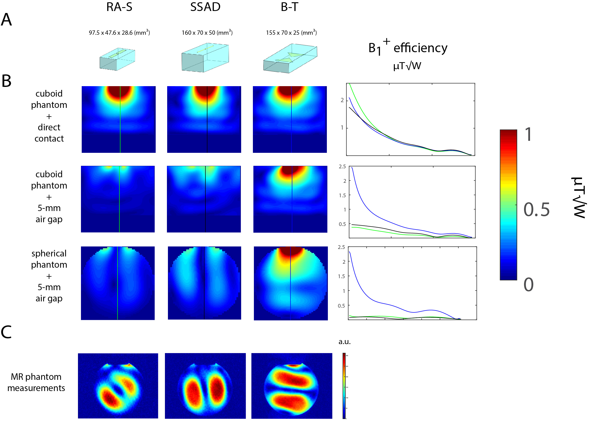
Figure 1: (A) Geometries of three different dipole antennas shortened
using D2O: R-S, SSAD and B-T. (B) B1+ distribution in
cylindrical and spherical phantom shown in two setups: direct contact
between DB and phantom (setup A) and 5-mm gap between DB and phantom (setup B).
(C) Phantom images obtained using SA2RAGE (only related to B1+ maps, but it is apparent that our simulations are confirmed). Each image was separately scaled to visualize the differences. Inaccuracies arise from: DB and phantom shells, air cavity, imperfections of prototypes (antenna feed, no shield in simulations).
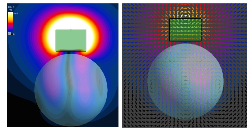
Figure 2: (Left) Spherical phantom, axial view: B1+ distribution within DB and the phantom. The
field stays within DB and does not propagate down to the phantom (null along
the center line). Only magnetic field, that is symmetrically “leaking” from
both sides of DB, reaches the phantom. (Right) H-field vectors. They are not orientated
dipole-like within the phantom.
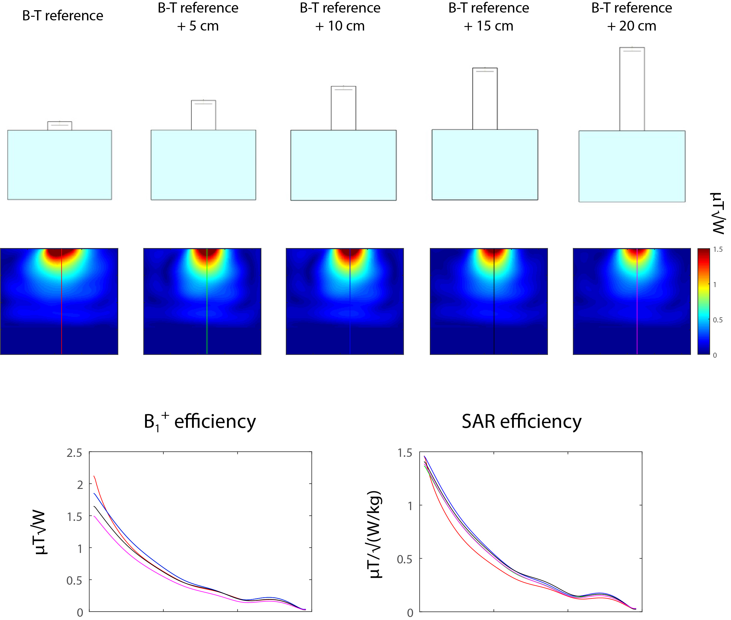
Figure 3: Element B-T with variable DB height in
case there is direct contact between DB and the cuboid phantom (setup A). Even
for 20-cm higher DB, very good B1+ and SAR efficiency is
observed. The effect is not proportional to the height, though. The optimal
value for this particular geometry can be found around 12.5 cm (total DB
height).
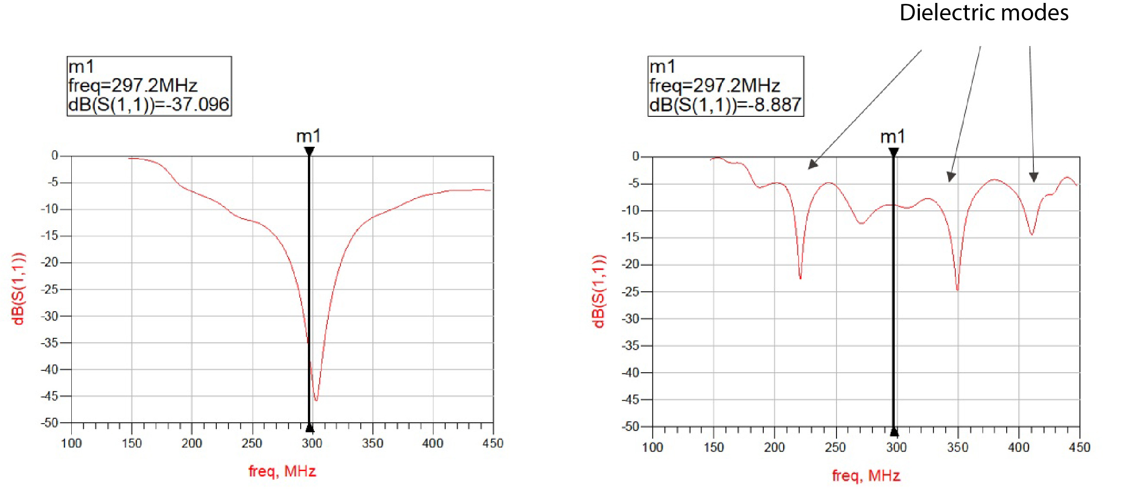
Figure 4: Scattering parameter matrix for B-T element
(height = 20 cm): direct contact (setup A: plot on the left hand side) and 5-mm
air gap (setup B: plot on the right hand side). Tuning and matching was
performed for setup A, and it was not adjusted for setup B. Tuning and matching
is straightforward for setup A (regardless the DB height). In case of setup B,
there are multiple resonances which represent various dielectric modes (or
combinations of modes) for given DB.
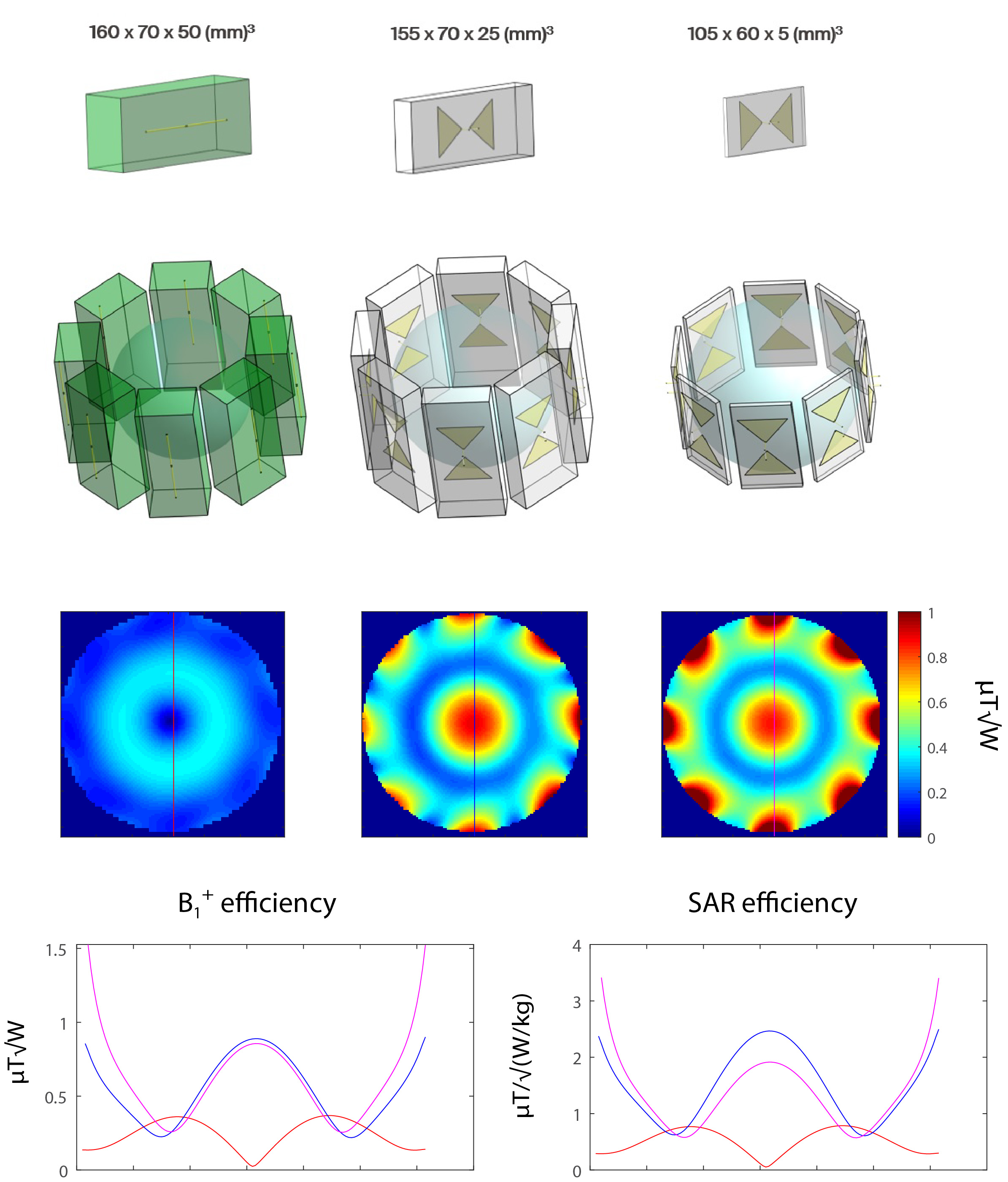
Figure 5: Transmit field distribution in
spherical phantom for three different 8-channel DA arrays driven in CP mode:
SSAD, B-T and B-T-m. Unlike B-T, DA in B-T-m is placed on the top of DB. As
expected, 8-channel SSAD array does not provide efficient magnetic field in the
center of the phantom. Reducing the height (C and D), significantly improves B1+
efficiency. Substantial change in overall dielectric block dimensions (B-T-m)
gives only 3% lower B1+ efficiency in the center of the
phantom than B-T, while providing much higher B1+
efficiency in the surface regions.