4082
The displacement current wave on a high dielectric constant (HDC) helmet and its effect on B1 Field at 10.5 T (447 MHz)
Navid Pourramzangandji1, Sebastian Rupprecht2, Myung-Kyun Woo3, Michael Lanagan4, Bei Zhang5, Riccardo Lattanzi5, Russell L. Lagore3, Jerahmie Radder3, Gregor Adriany3, Brian Rutt6, Kamail Ugurbil3, and Qing Yang1
1Department of Neurosurgery, PennState University College of Medicine, Hershey, PA, United States, 2HyQ research Solution, State College, PA, United States, 3Department of Radiology, Center for Magnetic Resonance, University of Minnesota Research, Minneapolis, MN, United States, 4Department of Engineering Science and Mechanics, Pennsylvania State University, State College, PA, United States, 5Department of Neurosurgery, The Bernard and Irene Schwartz Center for Biomedical Imaging, New York University, New York, NY, United States, 6Radiology, Stanford University, Stanford, CA, United States
1Department of Neurosurgery, PennState University College of Medicine, Hershey, PA, United States, 2HyQ research Solution, State College, PA, United States, 3Department of Radiology, Center for Magnetic Resonance, University of Minnesota Research, Minneapolis, MN, United States, 4Department of Engineering Science and Mechanics, Pennsylvania State University, State College, PA, United States, 5Department of Neurosurgery, The Bernard and Irene Schwartz Center for Biomedical Imaging, New York University, New York, NY, United States, 6Radiology, Stanford University, Stanford, CA, United States
Synopsis
We observed a propagating wave of displacement current on a continuous high dielectric constant (HDC) helmet at 10.5T with an eight channel dipole array in CP mode. As a secondary current source of B1, the distribution and phase retardation of the displacement wave on the helmet leads to an interesting problem for utilizing HDC material for B1 enhancement. We extracted the B1+ field originated by the HDC helmet by subtracting the primary field (within the human head model without helmet) from the total field (field in the presence of the helmet).
Introduction
The advent of 10.5T has pushed the limit of MRI resolution to a new level. In parallel, as it has been already shown for lower field MRI scanners 1, 2, that by using high dielectric constant (HDC) materials, we could achieve higher transmit efficiency and SNR, in this task, we investigate the effect of HDC materials at 10.5 T MRI scanners to enhance the transmit efficiency. The HDC material acts as a secondary source to enhance the B1+ field. However the amplitude and phase of this secondary source has never been studied, which is very critical to understand the effect of HDC helmet within the tissue/phantom under test. In this work, by performing simulations, we extracted the complex field created by the HDC helmet within the human head model.Methods
Simulation: All the simulations are performed in CST Microwave Studio as a full wave simulation package (source) using an Ella human head model 3. RF coil: The simulated RF coil is comprised of eight fractionated dipole antennae. To increase the electrical length of the antenna there is a meandered parts at each end of the dipole antenna. The whole length of each dipole is 180mm and is tuned to resonate at 447 MHz. Antennas are arranged over a Teflon cylindrical former with the diameter of 277 mm. Helmet-shaped HDC material has been employed to enhance the field strength. The helmet shaped is chosen as it is conformal to the shape of the head (Fig. 1). The thickness of the helmet is 8 mm and the relative permittivity is 50. The secondary field has been calculated in both magnitude and phase by subtracting the primary field in the head when the HDC helmet is absent from the total field when the HDC material is present. The B1+ maps, contributed to each of the channels, have also been investigated individually.Results and Discussion
As seen in Fig. 2a the displacement current formed a hurricane-like distribution that rotates in time following the coil’s quadrature B1 field in the HDC helmet. A persistently strong displacement current was formed on the top of the helmet for all phases, which leads to a strong B1 enhancement on top of the head. Because the higher permittivity of the helmet, the wave is traveling slower than in free space. Thus, the superposition of the field by the coil elements and the displacement current in the helmet will depend on the phase distribution of the displacement over the HDC helmet (Fig.2 b, c). Fig.2 show the B1+ field for baseline and the enhanced field after placing the HDC Helmet. As seen in Fig. 3, the amplitude and phase of the secondary field of each coil element, and its enhancement to the primary field distributed far away from the coil element over the entire slice or volume. As it is shown the field is not only improved near each coil element but also in the region as far as on opposite side. It can be seen that there is a dark band on the left side of the excited element (1st and 2nd row) which is related to the null field on the opposite side. It can be seen from the last row of Fig. 3 (for the phase of secondary B1+ field created by the helmet ) that the there is approximately 45 degrees phase difference between each column close to the coil element. This phase different can be compensated in quadrature mode (or B1+ shimming process) by applying -45 degree phase difference between adjacent elements. In quadrature mode the two loops of displacement current propagate clockwise on the helmet (Fig.3a) which acts as the secondary source. By exciting each individual coil element, Fig. 4 clearly shows the placement current wave propagates clockwise and counterclockwise in the HDC helmet, which enhanced the B1 field far from the coil elements.Conclusion
A propagating wave of displacement current can be formed on a continuous high dielectric constant (HDC) helmet at 10.5T. As a secondary current source of B1, the amplitude distribution and phase retardation of the displacement current wave on the helmet could enhance B1 far away from the primary current source. The wave behavior on the HDC material could not only impact the optimal design of the coil-HDC-helmet but also lead to a broader application for shaping/shimming the RF field at high field.Acknowledgements
This work is supported by NIH grant U01EB025144-03.References
[1] Yang, Q.X. et al., JMRI, 2013. 38(2).
[2] Rupprecht, S., et al., Magnetic Resonance in Medicine, 2017. 79(5).
[3] Andreas, C, et al. Physics in Medicine & Biology, 2010. 55(2)
Figures
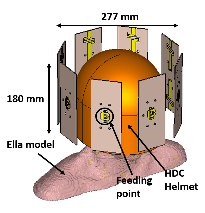
Fig.1 The simulation setup
including 8 fractionated dipole antenna array, HDC helmet and head model (Ella).
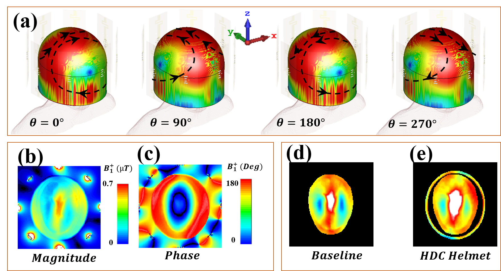
Fig.2 a) The displacement current at
different phases, b, c) amplitude and phase of the secondary field created by
the HDC helmet in quadrature mode, d) the B1+ field within the head for
baseline, and e) in the presence of HDC Helmet.
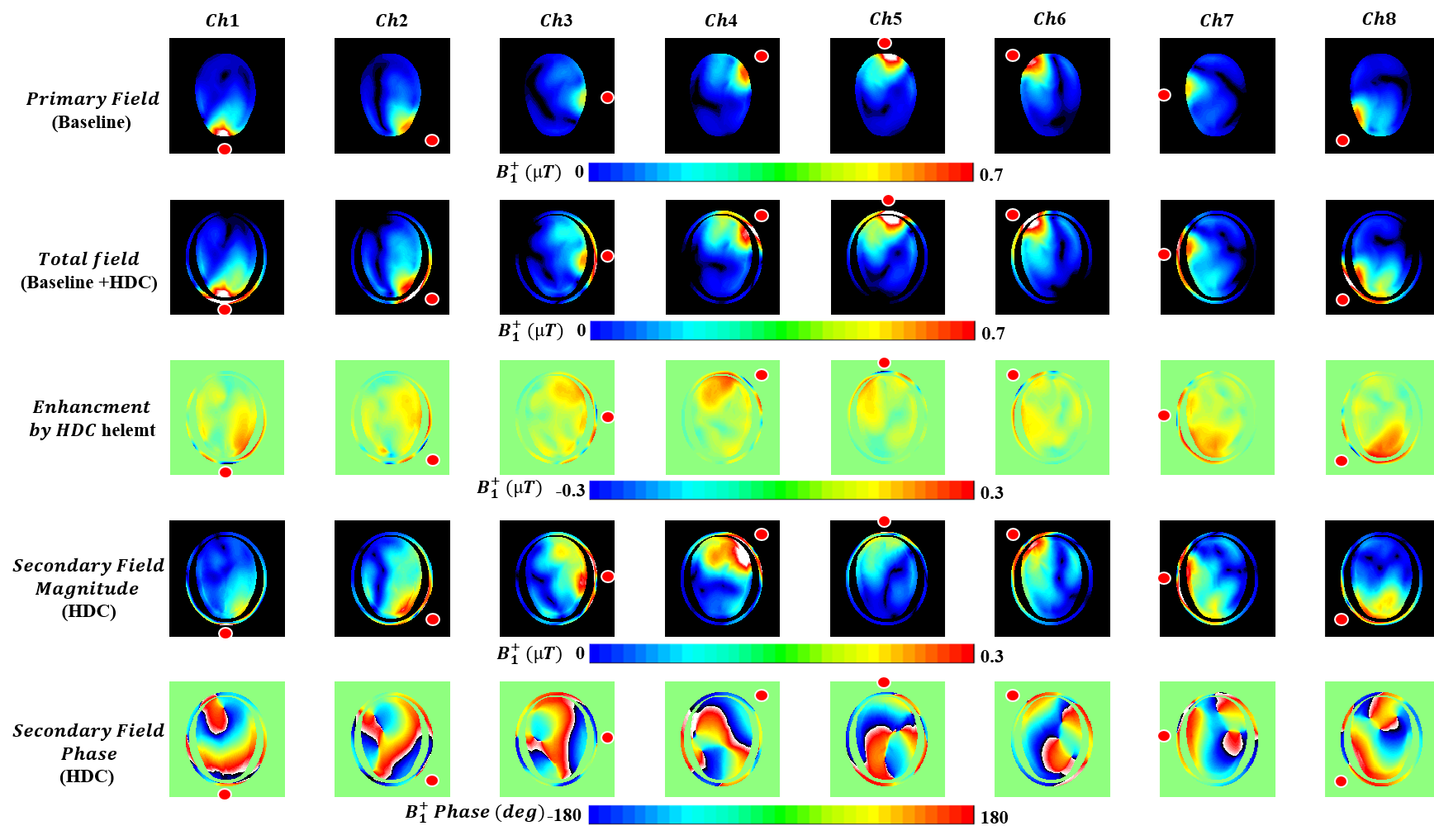
Fig.3 B1+ maps of each
channel (red dots) within the head in the transvers plane without (top) and
with (second row) HDC helmet. The enhancements by HDC (third row) for each
element were distributed into a widespread regions. The amplitude and phase (4th
and 5th row) of the secondary field by HDC helmet are highly
distributed into regions far from the primary coil elements.
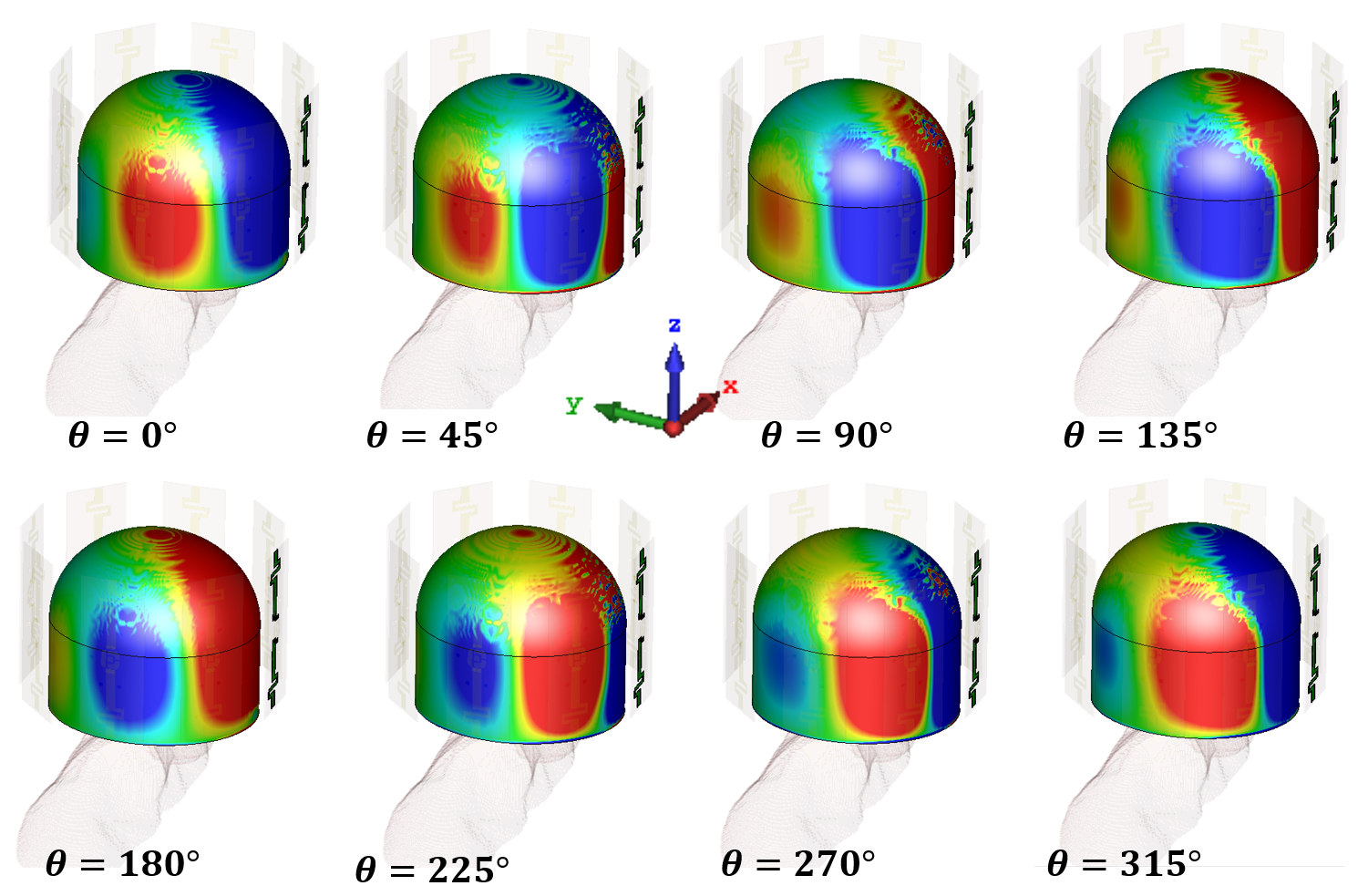
Fig.4 Different phases of
the displacement current wave (Jz) induced by one channel propagating around
helmet.