4077
Feasibility of Forward and Reversed Preamplifier Decoupling (FPD and RPD) Techniques for a Low Field MRI System at 1 MHz1Department of Radiology and Biomedical Imaging, Yale University School of Medicine, New Haven, CT, United States
Synopsis
This study investigated the feasibility of applying forward and reversed preamplifier decoupling techniques for low and high impedance coils, respectively, at 1 MHz. At a low field MRI, e.g. 1 MHz, the choice of components needed for interface circuitry together with availability of preamplifiers with low input impedance is challenging. In this study we demonstrated that using a high impedance coil with a lower number of turns achieved better decoupling levels than that of a low impedance coil. In addition, the minimum requirement for the input resistance of a preamplifier at 1 MHz was investigated.
PURPOSE
Preamplifiers with low input impedance were used to eliminate the mutual coupling between coil elements in an array, by suppression of the induced current by neighbouring elements1. For a low impedance coil (LIC), the low input impedance of the preamplifier is transformed to a high impedance at the coil ports known as (forward) preamplifier decoupling (FPD) 2 while using a high impedance coil (HIC), the induced current is eliminated when the transformed impedance at the port is low dubbed as reversed preamplifier decoupling (RPD) 3. For both methods, a preamplifier with low input impedance is required. However, low input impedance preamplifiers for our system (1 MHz)4 are not commercially available, therefore it is important to estimate the minimum requirement for the input impedance of such a preamplifier with respect to the above decoupling techniques. In this work the feasibility of both techniques together with the input impedance requirement of a preamplifier for a low field MRI system at 1 MHz were investigated.METHODS
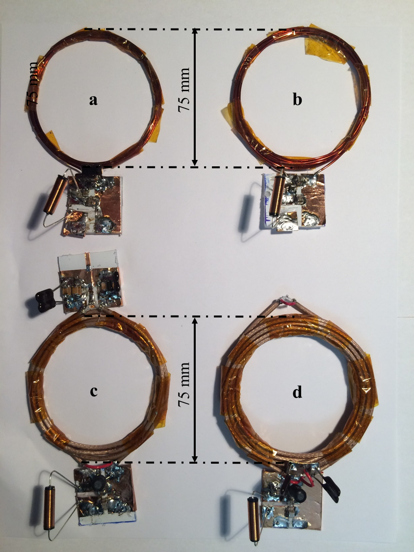
To evaluate the feasibility of FPD technique, two LICs with 5 and 10 turns and mean diameter of 75 mm were fabricated (Fig.1ab) using conventional copper wire. A matching network2 shown in Fig.2a was used to achieve 50 Ω noise matching while presenting high impedance at the coil port. The corresponding lumped elements values are provided in Table 1a. Since a higher number of turns are required to build HICs with 75 mm diameter at 1 MHz5, capacitors were added between the inner and outer conductor of the coaxial cable for 5turn and 10turn HICs (Fig.1cd). The matching circuitry for HICs was composed of an LC circuit and a phase shifter shown in Fig.2b and the corresponding component values are presented in Table 1b. Instead of using a very long cable3 (e.g. quarter wavelength at 1 MHz ~ 50 m), a lumped element, low-pass pi, phase shifter was used here as shown in Fig.1b. For the given phase , the ideal lumped element values are given as6$$L_{2}=Z_{0}\frac{\sin(\phi)}{\omega}$$
$$C_{2}=C_{3}=\frac{1-\cos(\phi)}{\omega Z_{0} \sin(\phi)}$$
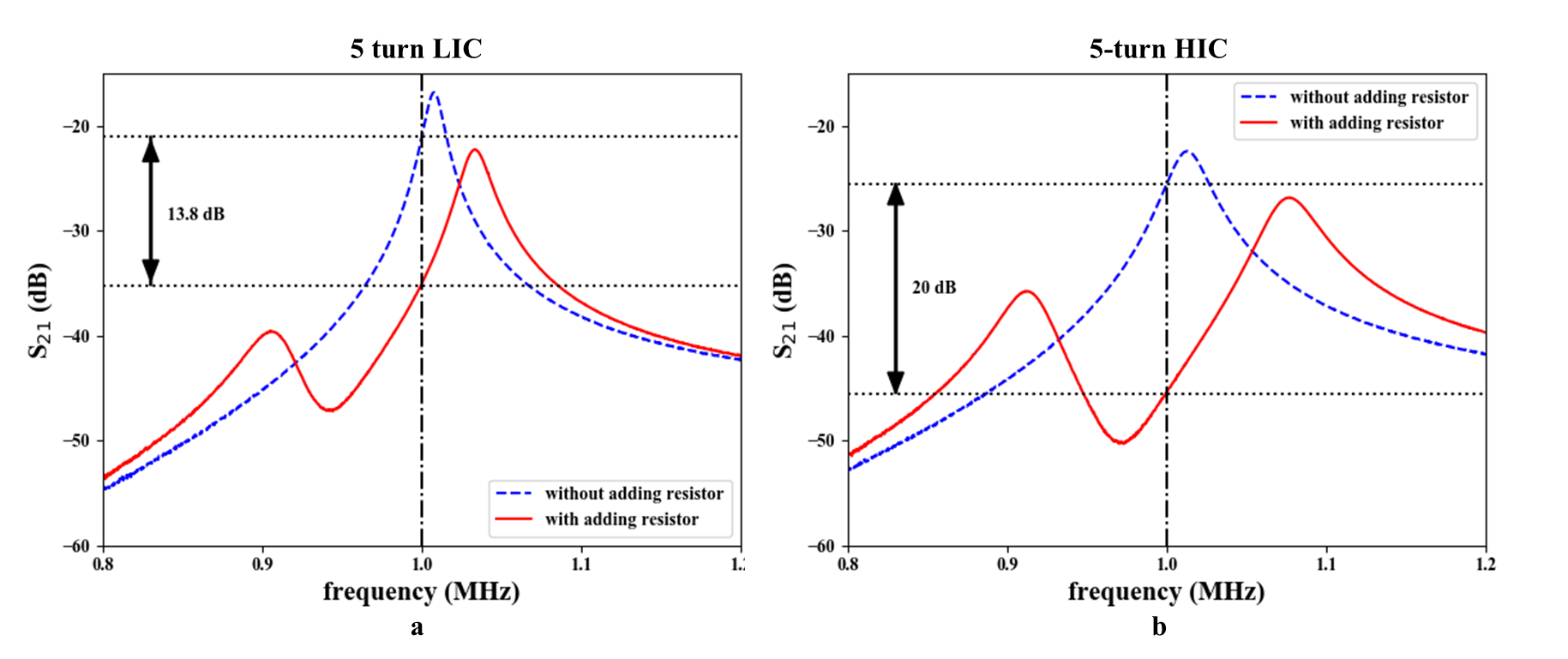
where Z0 is the characteristic impedance (50 Ω here) and ω is the angular frequency. On the bench, the values for the phase shifter components were adjusted to have the desired phase shift. Decoupling efficiency of each coil was evaluated using a decoupled double probe (< -70 dB) connected to a network analyser. Since, no preamplifier with low input impedance was commercially available at the time of experiments, the input impedance of the pre-amplifier was mimicked by resistors with 0.1, 0.5, 1, 2, 5, 10, 20 and 50 Ω. First, the S21 measurements were performed without any resistor presented at the output of matching and then a resistor was added each time at the matching circuitry output. The difference between without and with the added resistor (ΔS21) was used to evaluate the efficiency of each technique for each coil setup (Fig.3). In addition, Q-factor in the unloaded condition was extracted from the S21 measurement (impedance curve) of each coil to estimate the coil’s efficiency at 1 MHz.
RESULTS
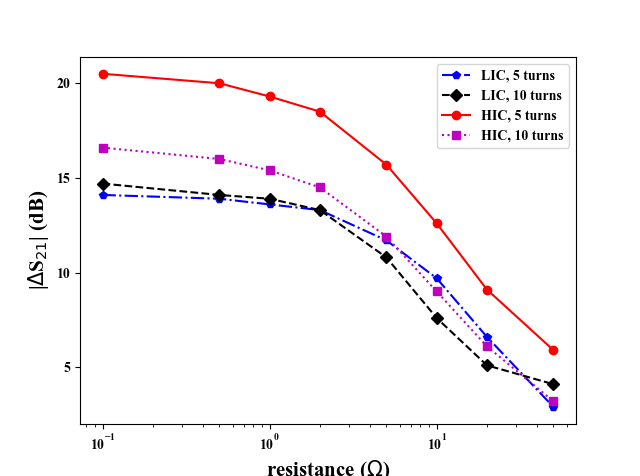
Figure 4 demonstrates the ΔS21 as a function of preamplifier input resistance for each coil setup. The 5turn HIC coil achieved better decoupling than the 10turn HIC and LICs specially for preamplifiers with an input resistance below than 2 Ω. For a 1 Ω input resistance, the 5turn HIC achieves 41% better decoupling than the 5turn LIC while for the 10turn HIC this value is improved by about 10 % compared to the 10turn LIC. Also Table 1 presents that the unloaded Q-factors for 5turn and 10turn HICs is reduced by 59% and 54 % in comparison with those of LICs.DISCUSSION
At such a low frequency, a pre-amplifier with very low input resistance (< 2 Ω) is required to achieve sufficient decoupling. However to improve the decoupling level in an array, preamplifier decoupling techniques can be used in combination with other decoupling approaches such as overlap decoupling. The Q-factor reduction for the HICs can be attributed to the losses of the added capacitors between the inner and outer conductor of the coaxial cable used to tune its self resonance frequency to 1 MHz as well as the type of the coaxial cable. The coil loss dominates sample loss at this frequency7, therefore the unloaded Q-factor values should not decrease when presenting a load. Depending on the availability of the low input impedance preamplifiers for 1 MHz, a suitable design and preamplifier decoupling technique considering coil’s efficiency should be chosen.CONCLUSIONS
At 1 MHz, feasibility of the FPD and RPD was studied for LICs and HICs, respectively. This study demonstrated that preamplifiers with an input impedance higher than 2 Ω led to rapid decreases in the decoupling level. The RPD technique employing a HIC with lower number of turns resulted in a more efficient decoupling than FPD with LICs. The output of this study will be used for design of low input impedance preamplifiers and a receive coil array targeting breast MRI at 1 MHz.Acknowledgements
No acknowledgement found.References
1. P. B. Roemer, W. A. Edelstein, C. E. Hayes, S. P. Souza, and O. M. Mueller, “The NMR phased array,” Magn. Reson. in Med., vol. 16, no. 2, pp. 192-225, 1990.
2. A. Reykowski, S. M. Wright, J. R. Porter, “Design of matching networks for low noise Preamplifiers”, Magn. Reson. in Med., vol. 33, no. 6, pp. 848-852, 1995.
3. B. Zhang, D. K. Sodickson, and M. A. Cloos, “A high-impedance detector-array glove for magnetic resonance imaging of the hand,” Nat. Biomed., vol. 2, no. 8, pp. 570-577, May, 2018.
4. R. Todd. Constable, C. Rogers III, B. Wu, K. Selvaganesan, and G. Galiana, “Design of a novel class of open MRI devices with non uniform B0, field cycling and RF spatial encoding” Proc. Intl. Soc. Mag. Reson. Med. 27, 2019.
5. L. Nohava, R. Czerny, R. Frass-Kriegl, J. Felblinger, J-C. Ginefri and E. Laistler, “Flexible multi-turn multi-gap coaxial RF coils (MTMG-CCs): design concept and bench validation”, Proc. Intl. Soc. Mag. Reson. Med. 2019.
6. R. J Weber, “Introduction to microwave circuits: Radio frequency and design applications", Wiley-IEEE Press, 2001.
7. L. Darasse, J-C. Ginefri, “Perspectives with cryogenic RF probes in biomedical MRI”, Biochimie, vol.85, no.9, pp.915-37, 2003.
Figures