4075
Optical Transmission of Digitized MRI Signals Using Delta-Sigma Modulation1Physics, Case Western Reserve University, Cleveland, OH, United States, 2EECS, Case Western Reserve University, Cleveland, OH, United States, 3Quality Electrodynamics (QED), Mayfield Village, OH, United States
Synopsis
The electromagnetic interference between conductive cables is becoming an issue as the number of MRI receive channels increases. Optical fibers are seen as one of the potential alternatives. Analog optical links have been investigated due to their relatively simple RF coils structure and minimum modification to the MRI system, but they are often limited by the electrical and optical nonlinearities and degradation of noise figure. In this study, we propose a digital optical transmission system based on delta-sigma modulation (DSM) that aims to provide high dynamic range (DR) for MRI signal transmission.
Introduction
Optical transmission of MRI signals has the advantage of being electromagnetic interference-free over traditional conductive cables. Various studies have been conducted to investigate the feasibility of analog optical links [1]–[7]. However, the dynamic range (DR) of analog optical links is hindered by electrical and optical nonlinearities as well as degradation of noise figure [8]. On the contrary, these problems would not be of concern for digital optical links [8], [9]. In this abstract, we propose a digital baseband-over-fiber transmission system based on delta-sigma modulation (DSM). DSM takes advantage of the fact that MRI signals are narrow-band. For a 3T MRI scanner, the signal bandwidth fB is typically 1 MHz centered around 123.3 MHz. DSM achieves high signal-to-noise ratio (SNR) by low-resolution quantization at a much higher sampling rate fs than the Nyquist frequency 2fB. The resulting over-sampling ratio (OSR) is defined as the ratio between the sampling rate and the Nyquist frequency. In addition, reconstruction of the analog signal after a DSM does not require a DAC. It can be performed simply by applying a low-pass filter to the quantized signal.Method and Experimental Setup
The block diagram of the complete baseband-over-fiber system is shown in Fig. 1. The radio-frequency (RF) input is first down-converted by the mixer to the baseband. The local frequency (LO) is generated by a programmable direct digital synthesizer (DDS). The DDS is programmed by a micro-controller to generate a local frequency (LO) close to the RF frequency and consequently produces a baseband signal after down-conversion. The latter is then digitized by the DSM using a high-frequency clock. A 1310 nm Fabry-Perot laser diode (LD) is driven by a constant bias current and modulated by the digital signal out of the DDS and NMOS switches, consequently producing a digital optical signal. After transmission over optical fiber, the optical signal is received by a PIN photodiode and first converted into current, then amplified and converted back to voltage by a trans-impedance amplifier (TIA). The TIA’s output is quantized by a comparator and sampled by a D-type flip flop to retime the data, i.e., remove any accumulated timing jitter. This digital signal is then low-pass filtered to recover the analog baseband signal. The circuit boards that implement the architecture above are shown in Fig. 2. The system is intended to incorporate a custom high-order high-sampling rate DSM chip (fourth order, fs = 100 MHz) to transmit and receive MRI signals with 1 MHz bandwidth and OSR = 50. This chip was designed and fabricated in 180 nm CMOS technology and is currently being tested. For a proof-of-concept demonstration, we instead use an RF signal with a 200 kHz bandwidth and a commercial second-order DSM with a maximum clock frequency of 20 MHz, resulting in the same OSR as the custom DSM chip. An active LPF with a cutoff frequency of 300 kHz is used at the receiver to recover the analog signal.Results
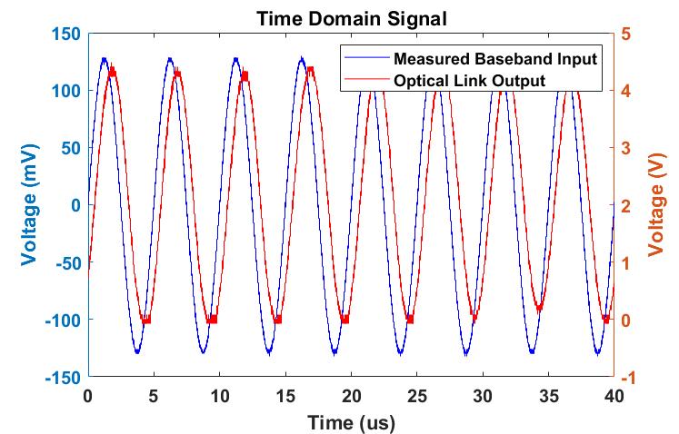
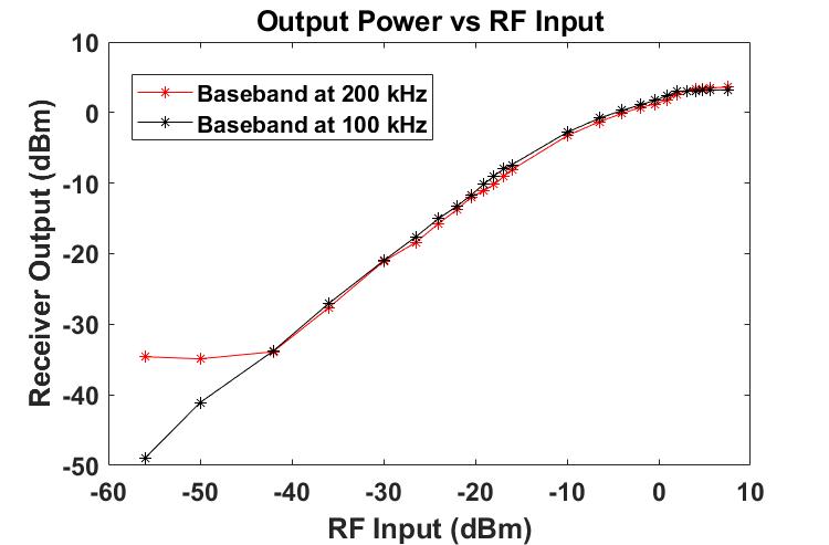
Fig. 3 compares typical measured baseband signals at the input (before DSM quantization) and output of the optical link. Fig. 4 presents the measured relationship between the RF input power level and the baseband output power for baseband frequencies of 100 and 200 kHz. The linear region for the 200 kHz signal is about 50 dBm, from −42 dBm to 8 dBm. The curve plateaus near −42 dBm mainly because of limited OSR. The linear region for the 100 kHz signal exceeds 64 dBm, from −56 dBm to 8 dBm, due to the higher OSR and thus lower quantization error.Discussion and Conclusion
The performance of the transmission system is highly impacted by the DSM, specifically its sampling rate. High sampling rate and low bandwidth would increase the dynamic range (DR). For an OSR around 50, the system has a measured DR (defined by a linear relationship between RF input and baseband output) of ~50 dBm. Lower baseband frequencies benefit from higher OSR, which reduces quantization error and increases DR. In addition, a balance is required between signal amplification before the DSM, the bias current that drives the laser diode, and the trans-impedance at the TIA to achieve the least signal distortion. We have designed and implemented a system for optical transmission of digitized MRI signals using delta-sigma modulation. Proof-of-concept tests were conducted for RF signals with limited bandwidth (<200 kHz) due to the sampling rate limitations of the commercial DSM. The importance of the DSM’s sampling rate in improving the dynamic range was demonstrated. Future work involves the evaluation of the transmission system’s performance using actual MRI signals from a 3 T scanner (~1 MHz bandwidth) and a custom DSM chip. The latter, which is currently being tested, is expected to greatly outperform the commercial DSM because of its high-order design and much higher sampling frequency (maximum of 100 MHz).Acknowledgements
This project has been supported by the Ohio Third Frontier, OTF IPP TECG20140138 and by Quality Electrodynamics, LLC.References
[1] J. Yuan, J. Wei, and G. X. Shen, “A 4-Channel Coil Array Interconnection by Analog Direct Modulation Optical Link for 1.5-T MRI,” IEEE Trans. Med. Imaging, vol. 27, no. 10, pp. 1432–1438, Oct. 2008.
[2] S. Biber, P. Baureis, J. Bollenbeck, P. Höcht, and H. Fischer, “Analog Optical Transmission of 4 MRI Receive Channels with high Dynamic Range over one Single Optical Fiber,” presented at the ISMRM 16th Annual Conference, Toronto, Ontario, Canada, 2008, p. 1120.
[3] G. P. Koste, “Integrated optical link for MR system,” US7508213B2, 24-Mar-2009. [4] J. Yuan, J. Wei, C. Du, and G. X. Shen, “Investigation of Dynamic Range Requirement for MRI Signal Transmission by Optical Fiber Link,” 2007.
[5] O. G. Memis, Y. Eryaman, O. Aytur, and E. Atalar, “Miniaturized fiber-optic transmission system for MRI signals,” Magn. Reson. Med., vol. 59, no. 1, pp. 165–173, 2008.
[6] G. P. Koste, M. C. Nielsen, T. R. Tolliver, R. L. Frey, and R. D. Watkins, “Optical MR Receive Coil Array Interconnect,” 2007.
[7] R. E. Gabr, M. Schär, A. D. Edelstein, D. L. Kraitchman, P. A. Bottomley, and W. A. Edelstein, “MRI dynamic range and its compatibility with signal transmission media,” J. Magn. Reson. San Diego Calif 1997, vol. 198, no. 2, pp. 137–145, Jun. 2009.
[8] L. M. Pessoa, J. S. Tavares, D. Coelho, and H. M. Salgado, “Experimental evaluation of a digitized fiber-wireless system employing sigma delta modulation,” Opt. Express, vol. 22, no. 14, pp. 17508–17523, Jul. 2014.
[9] A. Nirmalathas, P. A. Gamage, C. Lim, D. Novak, and R. Waterhouse, “Digitized Radio-Over-Fiber Technologies for Converged Optical Wireless Access Network,” J. Light. Technol., vol. 28, no. 16, pp. 2366–2375, Aug. 2010.
Figures