4074
An 8-channel Loop Coil Array for Body Imaging Using Coupled Line Phase Shifters at 7T
Haiwei Chen1, Lei Guo1, Aurelien Destruel1, Mingyan Li1, Ewald Weber1, Feng Liu1, and Stuart Crozier1
1School of Information Technology and Electrical Engineering, The University of Queensland, Brisbane, Australia
1School of Information Technology and Electrical Engineering, The University of Queensland, Brisbane, Australia
Synopsis
A large-size loop coil suffers from the current phase inversion along the loop surface and therefore weak the current intensity at the phase inversion points. A new RF coil using coupled line phase shifters is presented for body imaging at 7T MRI. This design can retain an in-phase current along the loop when the perimeter is larger than 1.5$$$\lambda$$$ ($$$\lambda$$$ is the wavelength in free space). An 8-channel coil array using this new design is simulated and compared with a conventional loop array. The results indicate that improved $$$B^{+}_{1}$$$ shimming can be achieved in a large region of interest.
INTRODUCTION
Ultra-high field (UHF) (≥ 7T) MRI has the potential for high signal-to-noise (SNR) ratio and enhanced tissue contrast1. However, due to the decreased radiofrequency wavelength at ultra-high fields, substantial wave effects exist and this can lead to $$$B_{1}$$$-field inhomogeneity2, 3. Therefore, it becomes challenging to design body coils for imaging a large region of interest (ROI) such as the torso. Although using RF coils with large physical size would be ideal, such designs are challenging. Specifically, the current distribution along the coil surface presents weakened points owing to the current phase inversion, thereby creating local dark regions of the $$$B_{1}^{+}$$$ field. This unfavourable phenomenon becomes more severe when the electrical length of the coil is further extended at UHF frequencies. In this work, a segmented loop coil is presented using coupled line phase shifters4, 5. This design aims to achieve a current distribution that is in-phase when the electrical length of the coil is larger than 1.5$$$\lambda$$$ at the operating frequency of 298MHz and consequently, improve the $$$B_{1}^{+}$$$ homogeneity over a large ROI.METHODS
As shown in Fig.1 (a), the length and width of the proposed coil is 600mm and 200mm, respectively. The coil is composed of two concentric segmented line loops which are symmetrically arranged. Both loops are made of several segments with identical length Ls (160mm), except the first two sections that connect to the feeding port of the inner loop (with L0 of 155mm). These two segmented line loops are separated with a distance of S (1mm) and were designed so the gaps between loop segments aligned with the centre of the other loop segments. The designed RF coil is mounted on a 0.5mm Rogers RO4003 substrate with dielectric constant of 3.55 and loss tangent of 0.0027. To demonstrate the performance of the design as a transmit RF coil for body imaging, full-wave simulations were conducted using CST Microwave Studio (Darmstadt, Germany). An 8-channel loop array was simulated by equally distributing the loops in a cylindrical contour with a diameter of 600mm (Fig.1 (b)). A homogeneous phantom was designed with width of 450mm, length of 800mm and height of 250mm, filling with body-like material ($$$ε_{r}$$$ = 35 and $$$\sigma$$$ = 0.4S/m). For comparison, a conventional loop coil with the same dimensions was also simulated. In all simulations, coil elements were tuned and matched for 7T imaging at 298MHz. The $$$B_{1}^{+}$$$ shimming process was performed with a custom algorithm run on MATLAB (MathWorks, MA, USA) by optimising the amplitude and phase of each channel.RESULTS and DISCUSSION
Fig.2 compares the simulated current distributions of the conventional loop coil and the proposed coil. It can be observed that current on the conventional loop presents a phase inversion near the centre of the coil, hence causing significantly weakened current intensity. However, the proposed coil is capable of retaining an in-phase current, thereby a nearly uniform current distribution can be achieved throughout the coil surface. This current distribution can help to improve the $$$B_{1}^{+}$$$ homogeneity inside the subject. Fig. 3 shows the $$$B_{1}^{+}$$$ field distribution from a single coil after normalizing its intensity by 1W accepted power at the excitation port. It can be seen that for the conventional loop coil, $$$B_{1}^{+}$$$ dark bands are observed in central coronal plane along x-direction and central sagittal plane along y-direction (Fig.3 (c) and (e)), due to out-of-phase current inducing a null current intensity. On the other hand, $$$B_{1}^{+}$$$ fields generated by the proposed coil exhibits an improved distribution along the z-direction (Fig.3 (d) and (f)). Consequently, magnitude of the normalized $$$B_{1}^{+}$$$ field in the central axial plane from conventional loop coil is significantly smaller than that from the proposed coil (Fig.3 (a) and (b)). The $$$B_{1}^{+}$$$ shimming results by using 8-channel coils in axial and coronal planes are shown in Fig.4. In circular polarization (CP) mode, both the conventional and proposed coils generated inhomogeneous $$$B_{1}^{+}$$$ field distributions. However, the proposed coil array can illuminate the central part of the phantom and shows stronger $$$B_{1}^{+}$$$ intensity in the central axial plane (Fig.4 (a)). Fig.4 (b) shows the shimming results after applying the optimized amplitude and phase to each excitation port of the coil array. It can be clearly observed that a uniform $$$B_{1}^{+}$$$ field distribution in a large ROI can be obtained by using the proposed coil array, whereas the conventional loop coil array presents an undesirable $$$B_{1}^{+}$$$ field distribution with several dark regions in the same ROI. The quantitative comparison of the $$$B_{1}^{+}$$$ field inside the ROI was given in Table.1. By using the proposed coil, the $$$B_{1}^{+}$$$ uniformity was improved by approximately 46% and 48% in axial and coronal planes, respectively.CONCLUSION
A novel design for a large RF body coil is presented, which has demonstrated the capability of producing an in-phase current distribution on the surface of a large loop coil. An 8-channel coil array has been simulated with a homogeneous torso phantom. Compared with the conventional loop array, significant improvements on both homogeneity and intensity of $$$B_{1}^{+}$$$ field can be observed.Acknowledgements
No acknowledgement found.References
- Nakada, Tsutomu. "Clinical application of high and ultra high-field MRI." Brain and Development 29.6 (2007): 325-335.
- Van de Moortele, Pierre‐François, et al. B1 destructive interferences and spatial phase patterns at 7 T with a head transceiver array coil. Magnetic resonance in medicine 54.6 (2005): 1503-1518.
- Röschmann, P. Radiofrequency penetration and absorption in the human body: limitations to high‐field whole‐body nuclear magnetic resonance imaging. Medical physics 14.6 (1987): 922-931
- Free, Charles E., and Colin S. Aitchison. Improved analysis and design of coupled-line phase shifters. IEEE Transactions on Microwave Theory and Techniques 43.9 (1995): 2126-2131.
- Schiffman, B. M. A new class of broad-band microwave 90-degree phase shifters. IRE Transactions on Microwave Theory and Techniques 6.2 (1958): 232-237.
Figures
Fig.1: (a) Configuration of the proposed coupled-line phase
shifter coil. The optimized dimensions are given in millimetres as: L=600, W=200, g=1, S=1, Ls=160, L0 =
155. (b) Simulation setup for the proposed 8-channel loop array with a
torso phantom.
Fig.2:
(a) Surface current distributions of the proposed coupled-line phase shifter
coil. (b) Surface current distribution of the conventional loop coil.
Fig.3:
Normalized B1+ field distributions for a single-channel using
the conventional loop coil and the proposed coupled-line phase shifter coil in
central axial plane (a) (b), central coronal plane (c) (d) and central sagittal
plane (e) (f).
Fig.4:
Shimmed B1+ field distributions in the central axial and
coronal planes for the 8-channel array composed of the proposed and the conventional
loop coils. (a): the shimming results by using the circular polarization mode.
(b): the shimming results by using the optimized amplitude and phase at each of
the excitation ports. The size of ROI is 200mm*150mm in the axial plane and 350mm*350mm
in the coronal plane, respectively.
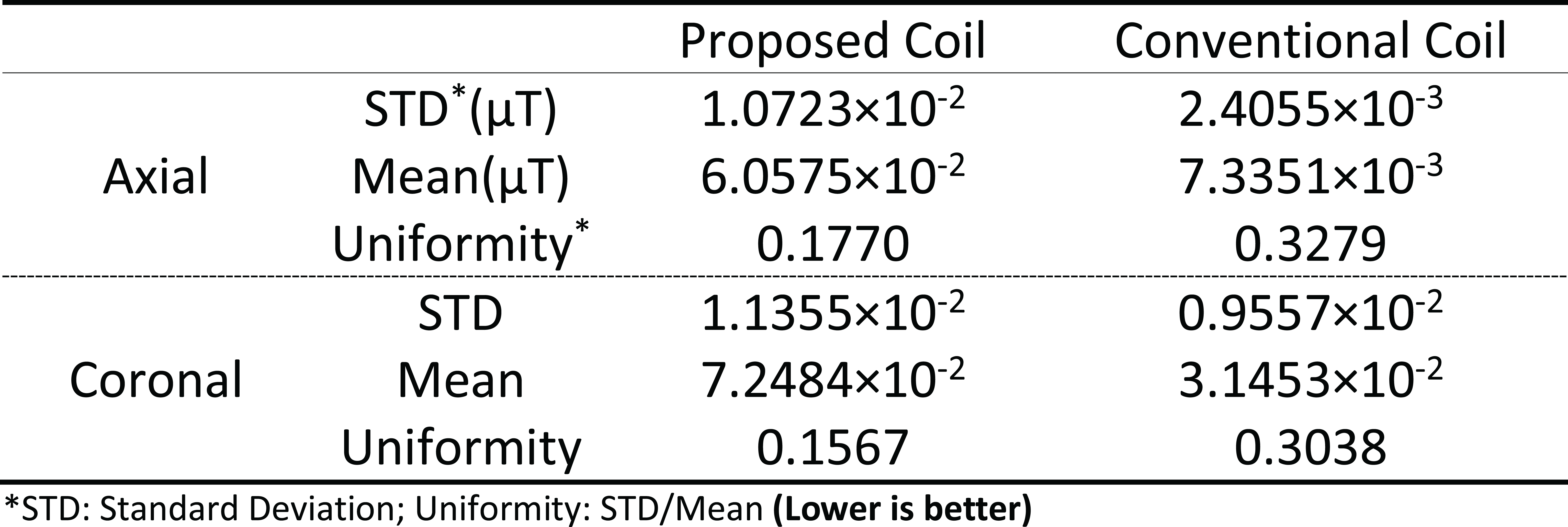
Table.1: Standard deviation, mean value and uniformity
of the B1+ fields in the ROI in the axial and coronal plane
for the proposed coil and convention coil, respectively. Please note the uniformity is
defined as $$$\frac{STD}{Mean}$$$ so that it is as lower as better.