4073
Experimental Realization of a Clinical Opencage Head Coil for Ultra-High Field MRI1Institut Langevin, ESPCI Paris, CNRS, PSL University, Paris, France, 2CNRS, Centrale Marseille, Institut Fresnel, Aix Marseille Univ, Marseille, France, 3CNRS, CRMBM, Aix Marseille Univ, Marseille, France, 4Multiwave Innovation SAS, Marseille, France, 5CEA, DRF, JOLIOT, NeuroSpin, UNIRS, Universit´e Paris-Saclay, Gif-sur-Yvette, France
Synopsis
A conventional birdcage head coil at 7T is not well suited for certain applications such as motion control. We propose an original coil based on a birdcage with a wide lateral aperture that provides access to the object under examination. We show that a sufficiently homogeneous magnetic field distribution can be obtained by optimizing the current distribution of such an “Opencage”. That coil was optimized using a full wave simulation and tested experimentally. The performance of an Opencage coil was compared to a commercial birdcage coil. Eventually, the Opencage coil is shown as a tradeoff between field homogeneity and access.
Introduction
Birdcage coils1 are one of the commonly used RF coil designs in clinical MRI and MRS today, even in ultra-high field imaging such as 7T. Recently, based on a metamaterial analysis, we have proposed a non-periodic birdcage-based coil design, the so-called Opencage that provides a free access to the object under examination. It can be used for placing a motion control tracking system2, and it offers a more comfortable environment for patients. A first small prototype with an inner diameter of 35mm, dedicated to preclinical imaging of rodent head, has been successfully tested in a 7T MRI system3. Here, the challenge was to develop a prototype with a much larger inner diameter of 260mm and working at 298MHz (7T) while still being able to sustain a circularly polarized (CP) mode.Methods and Theory
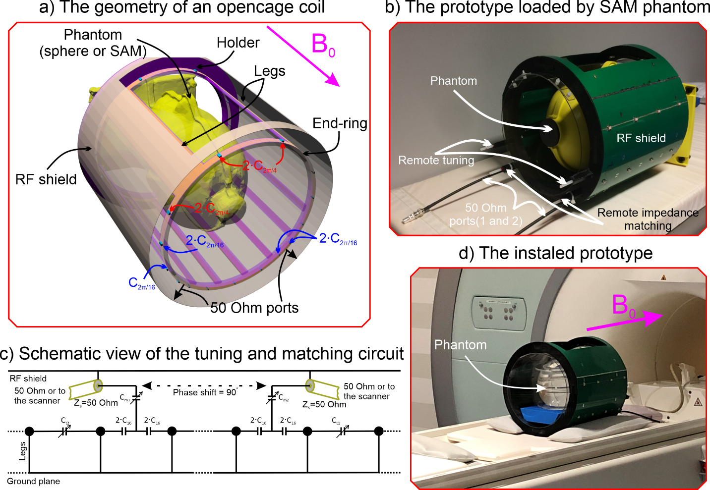
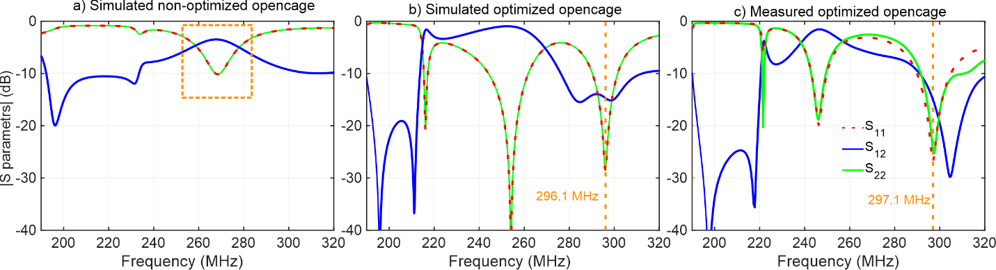
The bottom half of the designed Opencage is composed of eight identical legs (unit cell) that are parallel and equidistant (Fig. 1a). The top half contains only two identical cells. Two capacitors and a metallic ring connect the two extremities between two consecutive legs. As opposed to a conventional birdcage coil, the angles between two consecutive legs are not constant. Consequently, the relative phase shift of the currents between two consecutive legs should be 22.5° and 90° on the bottom and the top, respectively. To that end, we have optimized3 the capacities (C) and the inductances of the leg (L) and ring (Lr) of the transmission line model of the metamaterial. The optimized parameters to get the proper values of phase shift and a constant Bloch impedance3 for bottom cells are shown in Fig. 2. From these values we deduce that the width of the legs should equal 10 mm for the 8 bottom legs and 55mm for the 2 top legs. We have performed a full wave numerical simulation with a commercial finite element modeling based software (CST Studio Suite 2019) to finely tune the coil geometry. The coil was loaded by a homogeneous sphere phantom of 165mm diameter. Its permittivity was 75 and its conductivity 1.8S/m. The coil was driven in a quadrature regime by two 50Ohm ports that were on 90° distant legs at the bottom. The coil was shielded by a metallic cylinder with a 90° gap at the top (Fig.1a). Finally, the optimized Opencage coil was assembled and adjusted on bench (Fig. 1b) as well as inside the scanner (Fig. 1d). Opencage coil was tuned and matched using 4 variable capacitors (Fig. 1c). Very low reflection coefficients are obtained (S11 ≈ S22 ≈ -20dB) at 297.1MHz (Fig. 3c). The Opencage coil was tested with the aforementioned sphere phantom. Moreover, results were compared to a reference commercial CP birdcage coil working both in transmit and receive regime (Fig. 4). Due to the inability to connect simultaneously the 2 ports of the Opencage coil to the scanner, only one port was connected while the other one was connected to a 50Ohm load. The XFL sequence was used for flip angle (FA) mapping4.Results and Discussion
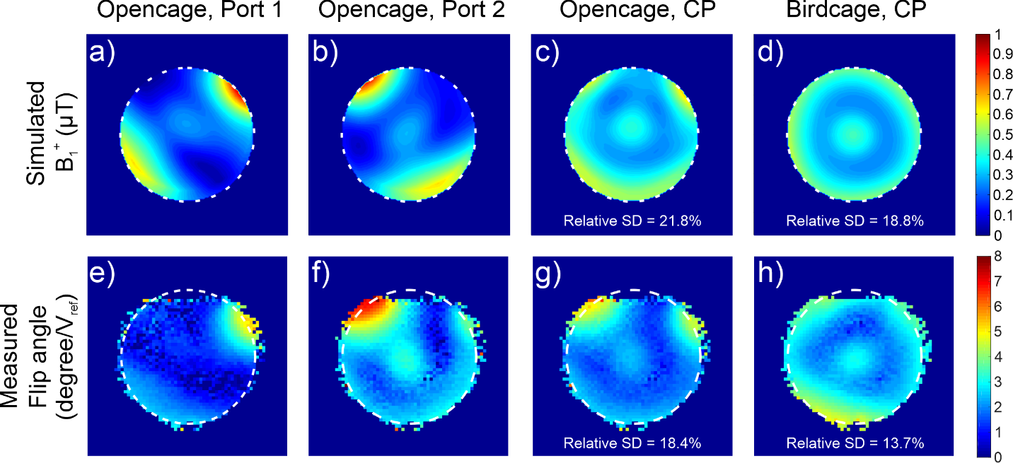
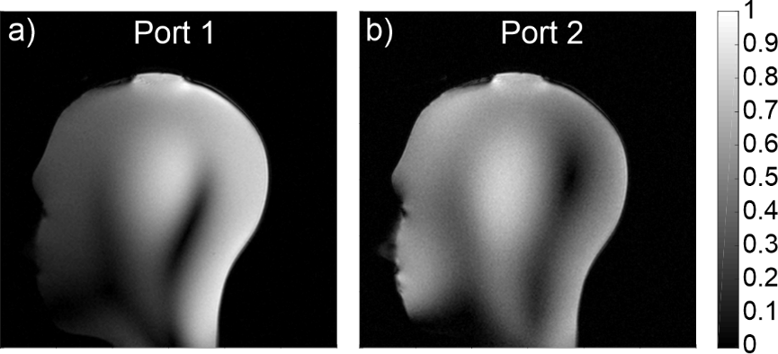
The simulations showed that without imposing a constant Bloch impedance3, the Opencage cannot be well excited (Fig. 3a). However, by optimizing both phase shift and impedance, the coil can be tuned and matched at the desired analytically predicted frequency (Fig. 3b) with good decoupling between the 2 ports (S12 ≈ -15dB). Two independent flip angle (FA) maps for the port 1 and 2 as well as the reconstructed CP mode of the Opencage coil and the map for the birdcage coil are shown in Fig. 4(e-h), and the comparison with the simulated B1+ maps is shown in Fig. 4(a-d). Circular polarized (CP) mode of the Opencage coil was reconstructed in post-processing and FA map was retrieved. The B1+ field homogeneity (relative standard deviation of B1+ field) is a little worse for the Opencage coil (21.8% in numerical simulation and 18.4% in experiment) than for the birdcage coil (18.8% in numerical simulation and 13.7% in experiment). Indeed, it is the consequence of a smaller number of legs in the case of the Opencage coil. In Fig. 5 we show preliminary images of the head phantom acquired with the Opencage coil.Conclusion
We have designed the Opencage coil that provides wide aperture giving access to the object under examination. The current distribution in the Opencage coil has been optimized using a metamaterial transmission line approach. This coil has been numerically validated by full wave numerical simulations. We have assembled and tested this coil on a phantom in a clinical 7T scanner. The B1+ homogeneity of the Opencage coil was demonstrated comparable to that of a conventional birdcage coil. Such Opencage head coil also offer better comfort for patients and are especially suitable for a motion control tracking system at ultra-high field.Acknowledgements
This project has received funding from the European Union’s Horizon 2020 research and innovation program under Grant Agreement No. 736937. This work is supported by LABEX WIFI (Laboratory of Excellence within the French Program “Investments for the Future”) under references ANR-10-LABX-24 and ANR-10-IDEX-0001-02 PSL. This work has been supported by the Leducq Foundation (large equipment ERPT program, NEUROVASC7T project).
References
1. Cecil E. Hayes, William A. Edelstein, John F. Schenck, Otward M. Mueller, Matthew Eash. An Efficient, Highly Homogeneous Radiofrequency Coil for Whole-Body NMR Imaging at 1.5 T. Journal of Magnetic Resonance.1985;63:622-628.
2. R. Frost, P. Wighton, F. Karahanoglu, R. L. Robertson, P. E. Grant, B. Fischl, M. D. Tisdall, and A. van der Kouwe. Markerless high-frequency prospective motion correction for neuroanatomical MRI. Magn. Reson. Med.2019;82:126–144.
3. A. Nikulin, J. de Rosny, K. Haliot, B. Larrat, and A. Ourir. Opencage radio frequency coil for magnetic resonance imaging. Appl. Phys. Lett. 2019;114:053503.
4. H-P. Fautz, M. W Vogel, P. Gross, A. B. Kerr, Y. Zhu. B1 mapping of coil arrays for parallel transmission. Proc. Intl. Soc. Mag. Reson. Med. Toronto. 2008:1247.
Figures