4072
A 2kW RF power amplifier for 7T proton imaging with digital pre-distortion1Erwin L. Hahn Institute for MRI, University of Duisburg-Essen, Essen, Germany, 2High-Field and Hybrid MR Imaging, University Clinic Essen, Essen, Germany, 3Medical Physics in Radiology, German Cancer Research Center (DKFZ), Heidelberg, Germany, 4Faculty of Physics and Astronomy and Faculty of Medicine, University of Heidelberg, Heidelberg, Germany
Synopsis
A 2 kW peak RF amplifier for 32-channel 7T proton imaging is presented. It is equipped with a digital pre-distortion providing a high linearity up to peak output power. The amplifier can be used for signal bandwidths of 1 MHz, making it suitable for almost any proton MR application.
Introduction
Body MR imaging at high fields of 3 Tesla and above poses high demands on linearity and peak output power of the RF transmit amplifiers. While 3 T MRI systems are equipped with peak transmit amplifiers capable of >30 kW in total, ultra-high field (UHF) systems are usually equipped with a 1 kW peak power amplifier per channel at a channel count of 8-32 (1). Body imaging, however, is especially demanding in terms of RF power when standoff arrays are used (2-4). To increase the total output power of a 32-channel transmit system to 64 kW for large field of view body imaging, we have developed a 2 kW RF power amplifier module with digital pre-distortion.Methods
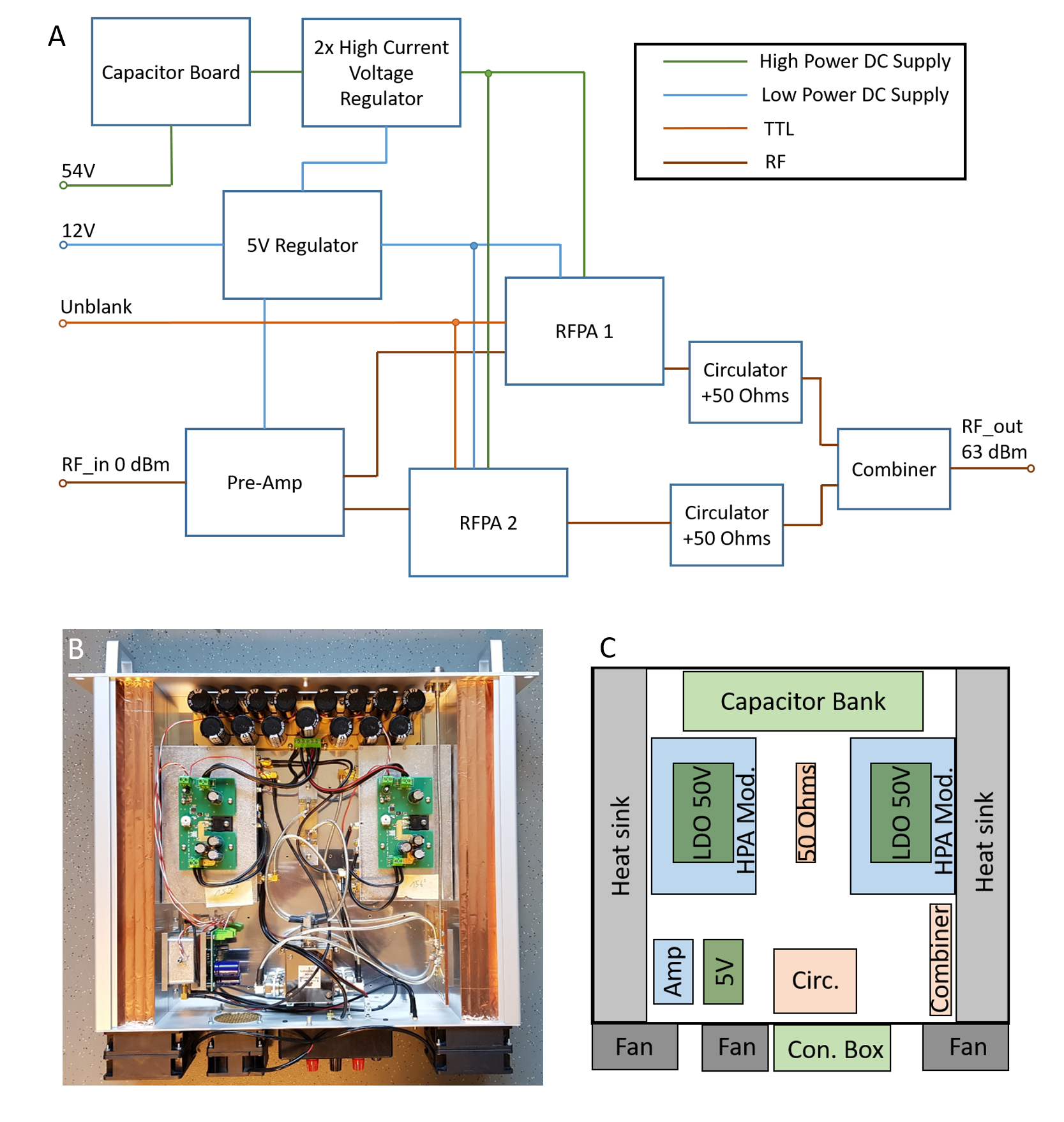
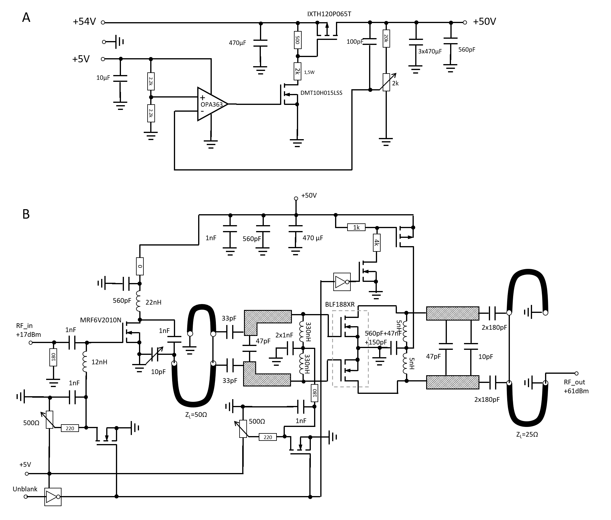
The power amplifier is composed of several modules. A schematic overview is shown in Figure 1A. A capacitor array of 102 mF is loaded with 54 V for peak power supply. Two high-current voltage regulators supply 50 V for two power amplifier modules with 1 kW peak power each. The RF input signal is amplified in a pre-amplifier stage with a 1:2 splitter by a factor of 19 dB before being fed into the power amplifier modules. A circulator at the output of each amplifier module ensures stability independent of reflected power. The RF signal is then combined in a shielded micro strip Wilkinson power combiner. A low-power regulator provides 5 V for gate bias voltages and logic from a 12 V source. Figure 1B shows a picture of the interior of the amplifier’s 19” housing with a height of two rack units. Figure 1C shows schematically where the components are located. Heat is transported via a 6 mm aluminum plate onto which all components, including the heat sinks, are screwed.The operational amplifier of the high-current voltage regulator (Figure 2A) compares the output voltage to a fixed reference voltage (5 V from the regulator) and controls the gate voltage of a high-power p-channel MOSFET (IXTH120P065T, IXYS, Milpitas, CA, USA).
The high-power RF amplifier module (Figure 2B) consists of a pre-stage (MRF6V2010N, NXP, Eindhoven, The Netherlands) and a high-power LDMOS output stage (BLF188XR, Ampleon, Nijmegen, The Netherlands). Without the unblank signal applied, the gate bias voltages are set to 0 V and drain voltage of the output stage is disconnected.
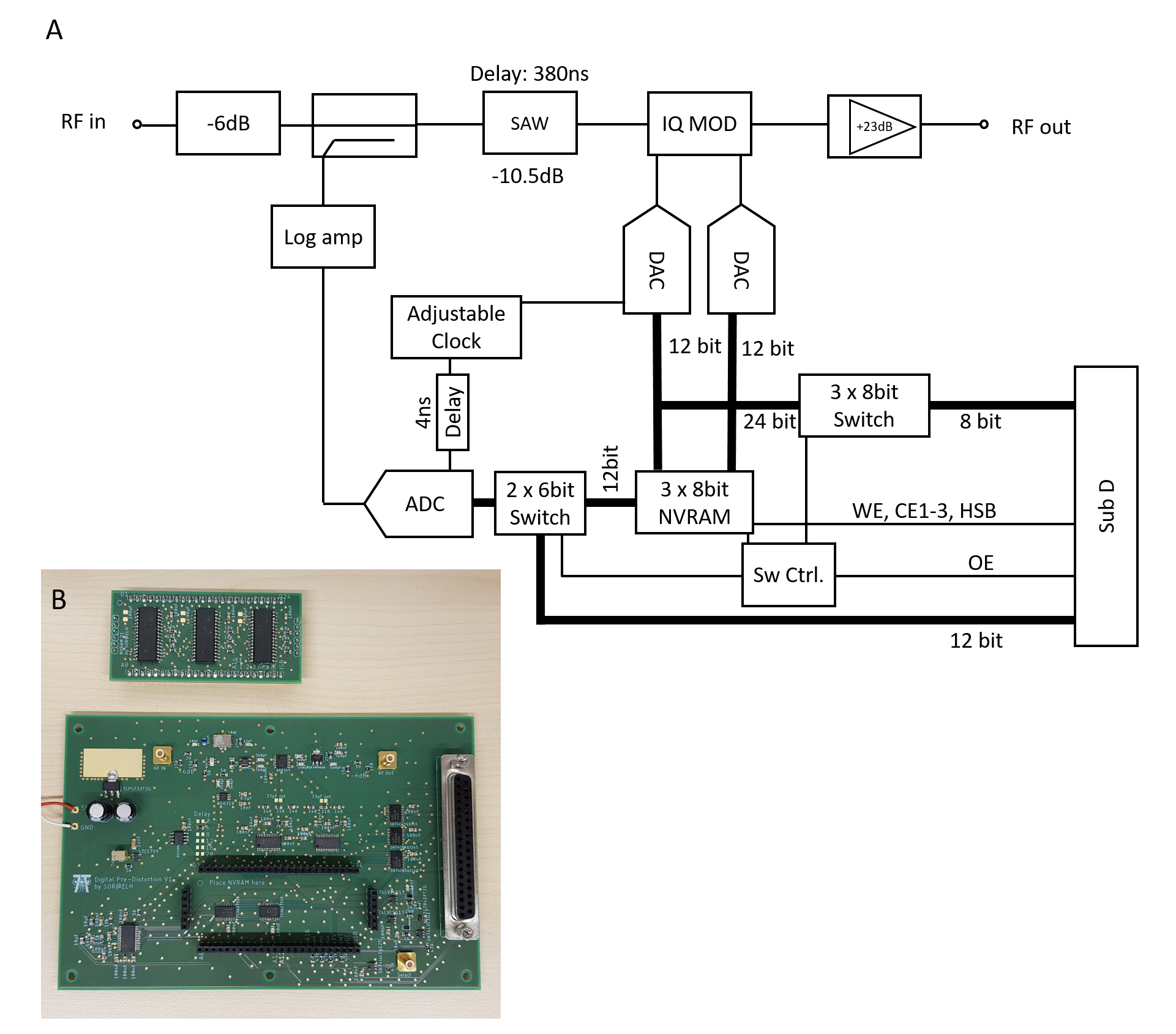
To linearize the amplifier, a digital pre-distortion was developed. Figure 3A shows the schematic. The input signal is split up, with one part going to a logarithmic amplifier. The logarithmized signal is digitized by a 12-bit ADC and the output word is fed into the address inputs of a nonvolatile RAM (NVRAM). The NVRAM contains correction values for each input power. These are fed to two DACs that provide the I and Q inputs for an IQ modulator. In this way, the RF input signal is distorted to counter the distortion of the high-power amplifier. To account for different delays in the digital and analog paths, a SAW filter with a delay of 380 ns is used in the analog path. Delay in the digital path is caused by conversion delay in the logarithmic amplifier, pipeline delay in the ADC, and the delay when updating the RAM output. Fine-tuning is achieved by changing the clock frequency.
The pre-distortion can be programmed via a 32-bit bus connected to a D-sub connector. After programming, the data remains in the NVRAM even when the power supply is shut down.
Figure 2B shows an image of the PCBs for the pre-distortion. The NVRAM is placed on a daughter board that can be plugged onto a socket.
Results
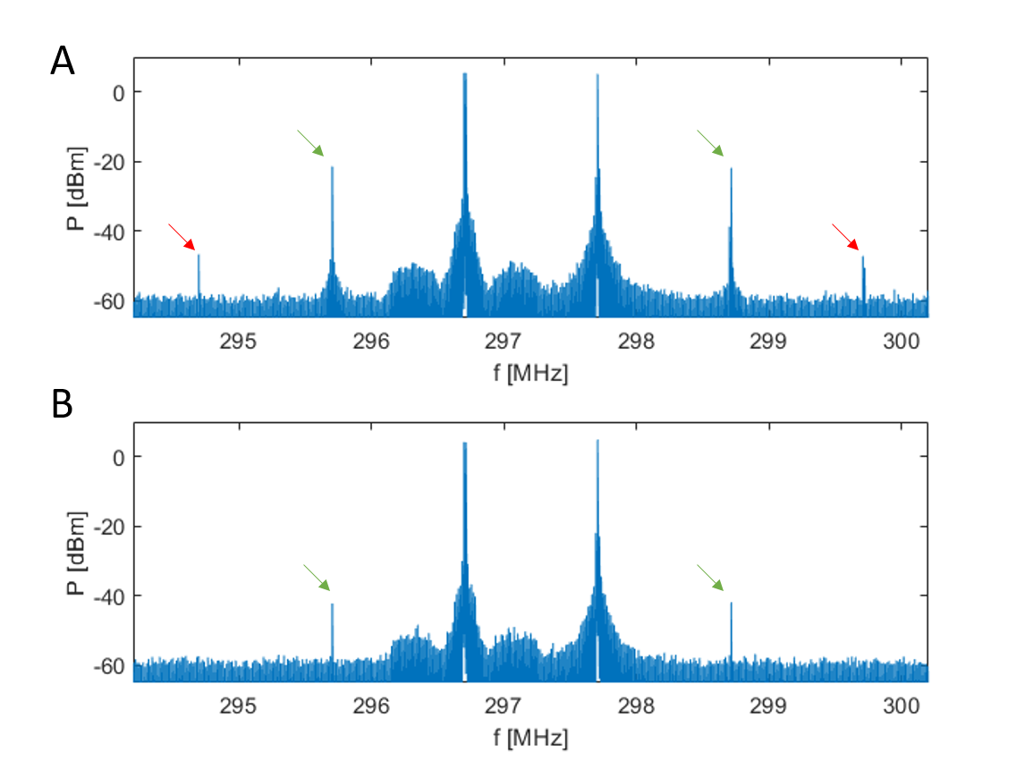
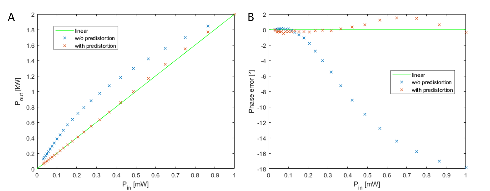
The amplifier has a maximum peak output power of 2 kW. Figure 4 shows the spectrum of an intermodulation measurement for a non-linear amplifier capable of continuous wave output. The input signals are 1 MHz apart. Figure 4A shows the spectrum without pre-distortion and Figure 4B the spectrum with pre-distortion. The 3rd-order intermodulation product is suppressed by 20 dB.Figure 5 shows the comparison of the output characteristics of the amplifier with and without the pre-distortion. With the pre-distortion, the amplifier shows very good amplitude linearity (maximum error 2%) up to its maximum output power (A), as well as a low phase error (B) (less then 2° maximum phase error).
While the amplifier itself can be used at frequencies ranging from 275 MHz to 307 MHz and could therefore be used for 1H and 19F, the SAW filter blocks signals below 286 MHz and therefore precludes the use of the amplifier for 19F.
Thirty-five power amplifiers with pre-distortion were built at a cost of less than $5,000 per piece.
Conclusion
A 2 kW peak RF amplifier for 32-channel 7T proton imaging is presented. In conjunction with the pre-distortion, the amplifier is very linear up to its peak output power. Furthermore, it can be used for signal bandwidths of 1 MHz, making it suitable for almost any proton MR application.Acknowledgements
No acknowledgement found.References
1. Erturk MA, Li X, Van de Moortele PF, Ugurbil K, Metzger GJ. Evolution of UHF Body Imaging in the Human Torso at 7T: Technology, Applications, and Future Directions. Top Magn Reson Imaging 2019;28(3):101-124.
2. Orzada S, Bitz AK, Gratz M, Johst S, Völker MN, Kraff O, Beyer D, Mathiebe T, Abuelhaija A, Solbach K, Ladd ME. An integrated 8-channel Tx/Rx body coil for 7 Tesla whole body MRI. in: Proceedings of the 23rd scientific meeting, International Society for Magnetic Resonance in Medicine, Toronto, p 630 2015.
3. Paska J, Cloos MA, Wiggins GC. A rigid, stand-off hybrid dipole, and birdcage coil array for 7 T body imaging. Magnetic Resonance in Medicine 2018;80(2):822-832.
4. Vaughan JT, Snyder C, Delabarre L, Tian J, Adriany G, Andersen P, Strupp J, Ugurbil K. Clinical Imaging at 7T with a 16 Channel Whole Body Coil and 32 Receive Channels. In: Proceedings of the 17th scientific meeting, International Society for Magnetic Resonance in Medicine, Honolulu, p 392 2009.
Figures