4071
Compact and Reproducible Microstrip Power Splitters for Array-Compressed Parallel Transmission at 7T1Department of Biomedical Engineering, Vanderbilt University, Nashville, TN, United States, 2Vanderbilt University Institute of Imaging Science, Nashville, TN, United States, 3Department of Radiology, Vanderbilt University, Nashville, TN, United States, 4Department of Radiology, Vanderbilt University Institute of Imaging Science, Nashville, TN, United States
Synopsis
Parallel transmission (pTx) with an array of radiofrequency (RF) coils enables spatially uniform excitation with lower SAR in high-field MRI. Performance improves with the number of coils. Currently, 7T scanners have a limited number of transmit channels due to their high cost and complexity. Array-compressed pTx (acpTx) networks comprise unequal power splitters that sit between the transmit amplifiers and coils, enabling a small number of channels to optimally drive a large number of coils. This study presents the design of low-loss unequal power splitter building blocks with minimal size that can be combined in stages for a variety of applications.
Purpose
Parallel transmission (pTx) with an array of radiofrequency (RF) coils enables more spatially uniform excitation with lower SAR in high-field MRI [1]. Currently, high-field MRI scanners have a limited number of transmit channels due to their high cost and complexity. Array-compressed pTx (acpTx) is a bolt-on method that enables a small number of transmit channels to optimally drive a large number of coils [2,3]. acpTx networks comprise unequal power splitters that sit between the amplifiers and coils [3]. This study presents a general, reproducible microstrip unequal power splitter design for 7 Tesla, which is optimized for minimal board size, low loss, and configurability for a wide range of power ratios. The boards were validated in bench tests and imaging experiments across a wide range of power ratios, in single-and multi-stage configurations.Methods
Design and SimulationThe Wilkinson unequal power splitter topology [4] was chosen for its low loss and small size, and the splitters were optimized for manufacture with RO3006 laminate (Rogers Corporation, Chandler, AZ) with a dielectric constant ε0 = 6.5 F/m. This material was chosen for its low loss and high degree of manufacturability at 7 Tesla [5]. The splitters were designed for a wide range of output power ratios (1:1, 1:2, 1:4 and 1:8); the design can be adapted easily for ratios between these. The impedance for each trace was calculated using the desired voltage ratio at the outputs of the splitter. These impedances, combined with dielectric thickness, dielectric constant, and copper weight, determined the trace widths. Figure 1 shows the simulations that were used to adjust trace length. Due to its high impedance, the 1:8 splitter required a defected ground structure (DGS) to improve its manufacturability. DGS’s increase the traces’ intrinsic inductance [6], which allows for wider and more easily milled traces. Shown in Figure 2, the splitters were designed in Autodesk Eagle (San Francisco, CA, USA). A novel microstrip network design was used to minimize the splitters’ size, enabling them to be included in a coil housing or cascaded in multiple stages. The designs are available on Github (https://github.com/wgrissom/RepRAPS) and can be reproduced as-is or reconfigured for output ratios between those presented here. The optimized design comprises a matrix of rings, each split into four equal length segments. The radius of the rings was calculated using the trace width, the length of the microstrip segment and an optimization coefficient related to the number of rings [7]. Compared to conventional unequal microstrip splitters, the electrical characteristics remain the same while the footprint is reduced many-fold.
Manufacture and Imaging Validation
Figure 1 shows that the power splitters were manufactured and bench tests were performed to validate the low-loss design at 298 MHz. Figure 3 shows that each ratio (1:1, 1:2, 1:4 and 1:8) was placed in a 7T Philips Achieva (Best, Netherlands) between the amplifier and a Nova (Wilmington, MA, USA ) birdcage coil. B1+ maps were collected for validation using the DREAM [8] method. The power splitters were designed such that they can be mixed and matched in a two-stage system to achieve a greater variety of power ratios for different applications.
Results and Discussion
Figure 1 shows a table of simulations, bench tests and manufactured boards across all ratios. The worst isolation between the output ports was -23.9 dB, -17.9 dB, -25.79 dB and -13.1 dB, respectively, and the worst match was -21.2 dB, -17.0 dB, -17.8 dB and -15.7 dB respectively. Figure 2b shows a two-stage cascaded power splitter, with a X:Y input stage and X:Y and X:Y output stages. The worst isolation between output ports was -20.8 dB (S45) and the worst match was -19.5 dB (S33). The measured 1:1 and 1:2 ratios were in good agreement with the expected ratios. Due to low signal from low power the 1:4 and 1:8 ratios were more difficult to verify. Figure 3 shows measured B1+ maps that verify the bench results inside the scanner. The loss ranged from 2-11% in comparing a reference scan to the 1:1 ratio. The 0 degree port of the birdcage coil was used for transmit while the 90 degree port was 50 ohm-terminated. This experiment demonstrated the network’s ability to use the microstrip circuit inside the scanner with practical power applied.Conclusion
Wilkinson unequal microstrip power splitters made with RO3006 laminate were optimized for small board size and low loss, across a wide range of power ratios. The splitters can be cascaded, output to input, into two stages while maintaining the expected ratios and low loss. This will enable the construction of a two-stage 8-channel-to-N-coil acpTx matrix with less than 7% power loss (including connectors) for applications such as MR Corticography.Acknowledgements
This work was supported by NIH Grants U01 EB 025162 and R01 EB 016695.References
1. Grissom, W. A., Sacolick, L., Vogel, M. W. (2010). Improving high-field MRI using parallel excitation. Imag Med,2:675–693.
2. Cao, Z., Yan, X., & Grissom, W. A. (2016). Array‐compressed parallel transmit pulse design. Magnetic resonance in medicine, 76(4), 1158-1169.
3. Yan X, Cao Z, Grissom WA. Experimental implementation of array-compressed parallel transmission at 7 Tesla. Magn Reson Med 2016;75:2545–2552.
4. Pozar, D. M. (2012). Microwave engineering. Hoboken, NJ :Wiley,
5. Gallego, G., Sappo C., Yan X., Grissom W. A. (2018) Design and manufacturing of microstrip power splitters for array-compressed parallel transmit MRI. In: 2018 Biomedical Engineering Society Annual Meeting, Atlanta, Georgia, USA; 2018 (Abstract 002669).
6. Lim, J. S., S. W. Lee, C. S. Kim, J. S. Park, D. Ahn, and S. Nam (2001). A 4 : 1 unequal Wilkinson power divider, IEEE Microwave and Wireless Components Letters, 11:124-126.
7. Popugaev, A. E., Wansch. A novel miniaturization technique in microstrip feed network design. In: 3rd Annual Conference on Antennas and Propagation of IEEE, Berlin, Germany; 2009 (INSPEC Accession Number 10698781).
8. Nehrke K, Bornert P. DREAM - A novel approach for robust, ultrafast, multislice B1 mapping. Magn Reson Med 2012;68:1517–1526
Figures
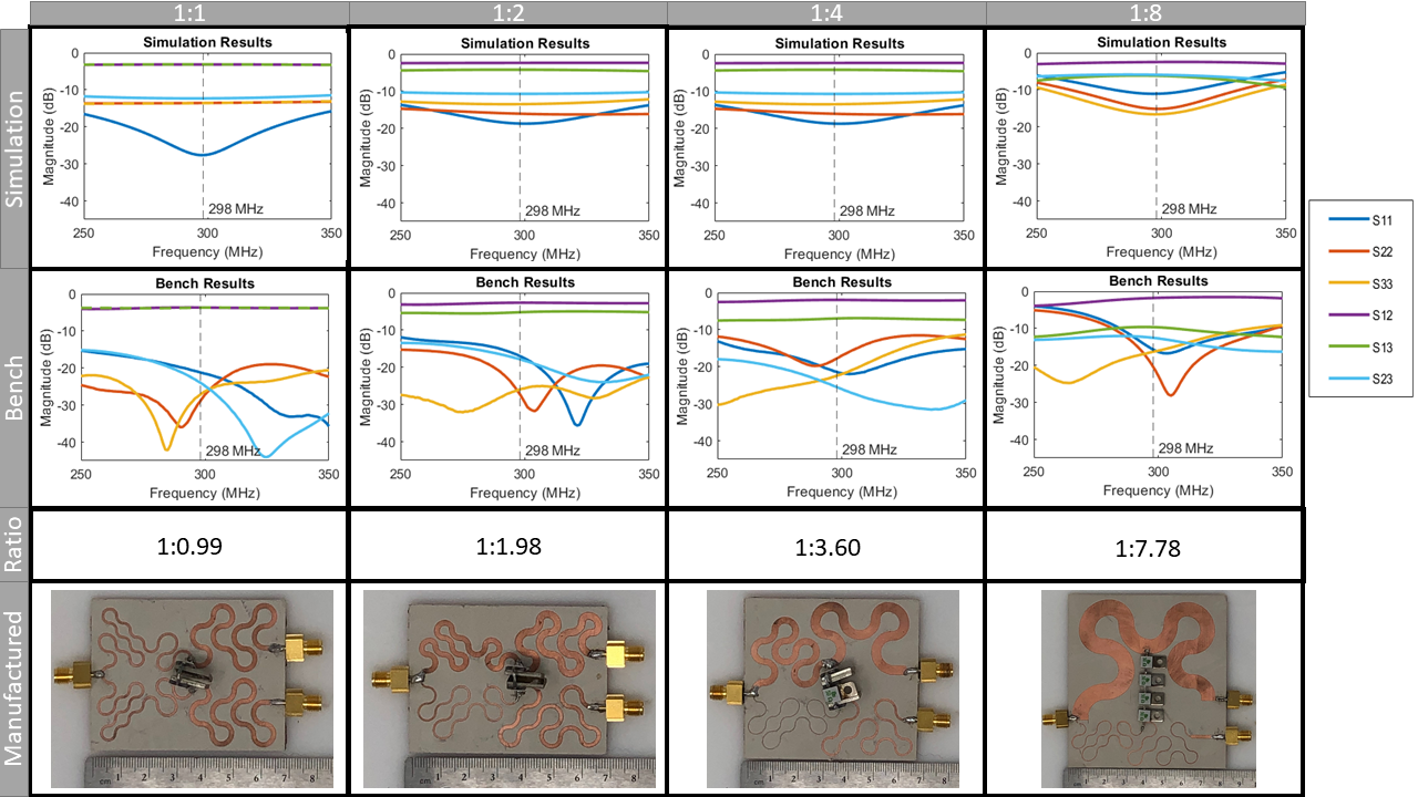
Figure 1. 1:1, 1:2, 1:4 and 1:8 ratio power splitters are able to be simulated in ANSYS HFSS (Canonsburg, PA, USA) and tested on a network analyzer (Agilent, Santa Rosa, CA, USA). The results from the simulations and the bench measurements are in good agreement. Bench measurements show that all matching is better than -15.5 dB and all ratios show a maximum of 0.33 dB loss (excluding connectors) which is less than 7%. The largest board is the 1:8 splitter with dimensions 8.8 x 8.2 cm. The smallest board is the 1:1 splitter with dimensions 6.9 x 5.2 cm.
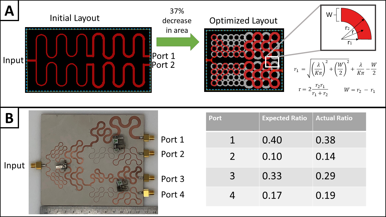
Figure 2.
A) A previous board design [5] is shown (left) in comparison to the new optimized design (right). The white circles detail the ring matrix that is determined by trace width. A quarter of the ring segment is blown up along with the equations used to calculate the ring’s radius.
B) The optimized layout allows the power splitters to be cascaded into two stages for a 4-way splitter. This improves manufacturability by reducing board size. The actual ratios of the two-stage power splitter are in good agreement with the expected values.
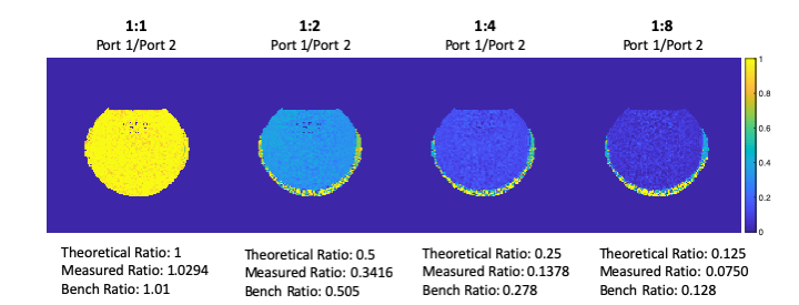
Figure 3. A mineral oil bottle phantom was imaged in a Nova (Wilmington, MA, USA) birdcage coil on a 7T scanner. B1+ maps were collected using the DREAM [8] method. The B1+ maps show the achieved power ratios 1:1.02, 1:2.93, 1:7.25, 1:13.33 compared to the desired 1:1, 1:2, 1:4 and 1:8 ratios. (TR = 1000ms, nominal flip angle = 30, NSA=1)