4069
Differential Mode Self-Decoupled Coils1Vanderbilt University Institute of Imaging Science, Nashville, TN, United States, 2Department of Radiology, Vanderbilt University Medical Center, Nashville, TN, United States, 3College of nuclear equipment and nuclear engineering, Yantai University, Yantai, China, 4Department of Biomedical Engineering, Vanderbilt University, Nashville, TN, United States
Synopsis
Self-decoupled coils (SDCs) were recently described which can solve complex coupling issues in dense arrays. SDCs have a simple structure and represent a general approach. However, dipole mode in SDCs make it sensitive to the load. In this work, we introduced a differential mode to the design of SDCs to alter the necessary value of Cmode and a coils’ robustness to loading. This differential-mode SDC can be seen as a combination of differential-mode decoupling with self-decoupling. We found that suitable Cmode can choose to increase coil robustness as well as avoid added coil loss.
Purpose
Self-decoupled coils (SDCs) were recently described which can solve the complex coupling issues that arise in a dense array, and which re-distribute impedances to precisely match electric couplings to cancel magnetic couplings [1]. SDCs have a simple structure and represent a general approach applicable to both transmit and receive arrays, as well as mixed arrays that combine loop coils with other elements such as dipoles. However, the dipole mode in SDCs makes it sensitive to the load. In this work, we introduce a differential-mode of operation for SDCs by adding a passive loop. The passive loop makes the dipole mode in SDCs become micrstripline mode. It also reduces the coil's self-inductance and thus increases the value of Cmode.Theory
Figures 1a-d illustrate differential-mode SDCs using different types of passive closed loops: Figure 1a uses circumferential shielding, Figure 1b uses a stacked passive loop, and Figure 1c uses an inner passive loop. The differential mode is generated by the inductive coupling between the SDC coil and the passive loop, and thus the contribution of the differential mode depends on the distance between the coil and the passive loop. It also should be noted that the differential mode decreases the coil efficiency because it constrains the magnetic field between the coil and the passive loops, so less magnetic flux goes outside to the sample. However the differential mode is beneficial because it reduces the self-inductance of the SDC, and thus increases the capacitance of coil (mainly Cmode). There is therefore a tradeoff between coil efficiency and the value of Cmode when choosing the distance between the SDC and the passive loop.Methods
The three differential-mode SDC types were modeled and simulated using Ansys software. The coil diameter was set to 6cm and operated at 298MHz (7T). The coil-to-passive loop distance was varied from a fraction of a mm to several mm: 0.25/0.5/1/2/3 mm for the inner passive loop case; 0.25/0.48/0.95/1.3/2.4 mm for the stacked passive loop case; 0.205/0.305/0.605/1.405/2.155 mm for the inner passive loop case, as shown in Figures 1d-f. For all cases, we simulated the scattering parameter S21 between two closely spaced side-by-side loops with various Cmode values (with coils well matched). A cuboid phantom (σ=0.6 S/m,εr=78, 40x15x15cm3) was placed 1.5cm below the coils as the load. Because the coil-to-passive loop’s distance changes the coil efficiency, we also simulated the B1 field of a single SDC with the optimal Cmode that ensures the best coil isolation. To evaluate the possible B1 efficiency decrease, we built a 6-cm-diameter non-optimized coil using semi-rigid coaxial cable (EZ86/CU/M17, Huber+Suhnerouter). The outer conductor was used as the coil element, and the inner conductor was the passive loop (they were 0.6 mm apart). For comparison, we also built a conventional SDC of the same size. GRE images were acquired of an ex-vivo squirrel monkey brain phantom using a 9.4T Varian system.Results
Figure 2 shows the values of the two coils’ transmission coefficients (S21) versus Cmode. When the coil and passive loop are closely spaced, the differential mode dominates and the EM fields are localized between them and do not go outside. Therefore, they are highly isolated for different values of Cmode. For instance, when the circumferential shielding is 1mm above the coils, their isolation can always achieve <-15 dB (Figure 2a). The localized fields and large Cmode increase the coil’s robustness versus loading. As shown in Figure 3, the maximum frequency shift of a coil with a stacked loop 0.25-mm apart is 4.6MHz, while that of an original SDC is up to 17.3MHz. However, the coil’s better robustness comes with a cost of lower efficiency. As shown in Figure 4b, its B1 efficiency is only 49% compared to an original SDC. As the passive loops are moved further away from the coil, the differential mode contributes less and the coil performance becomes similar to that of an original SDC. Similar to simulation results in Figure 3, the SNR from the non-optimized differential mode SDC is only 56% compared to that of an original SDC.Discussion and Conclusion
We introduced a differential mode to the design of SDCs to alter the necessary value of Cmode and a coils’ robustness to loading. This differential-mode SDC can be seen as a combination of differential-mode decoupling with self-decoupling. Note that the differential-mode itself can greatly improve the coil isolation with no need to select Cmode [2,3]. It induces considerable coil losses and decreases the SNR, as shown in previous works [2] and also validated here (Figures 4 and 5). By combing the differential mode with the SDC, there is a tradeoff between coil losses and Cmode values. For a 6-cm-diameter coil at 7T placed 1.5cm apart from a tissue-equivalent phantom, the B1 efficiency can be maintained with the coil-to-passive loop's distance >1.5mm. We note that this distance varies with different loading cases. Generally, it can be smaller with heavier loading but has to be larger in lighter loading cases. The dielectric between the coil and passive loop provides another degree of freedom (its relative permittivity) to manipulate the resonance frequency, and so the Xarm can be reduced for small self-decoupled coils at lower fields.Acknowledgements
The authors thank Dr. Feng Wang of Vanderbilt University for acquiring the in vivo images and Dr. Andrew Webb of Leiden University for helpful discussions on using the differential mode to improve the isolation of coaxial cable coils.
This work was partially supported by NIH Grant R01 EB 016695.
References
1. Yan, X., Gore, J. C., & Grissom, W. A. (2018). Self-decoupled radiofrequency coils for magnetic resonance imaging. Nature communications, 9(1), 3481.
2. Yeh, J. N. T., Lin, J. F. L., Li, Y. T., & Lin, F. H. (2018). A Flexible and Modular Receiver Coil Array for Magnetic Resonance Imaging. IEEE transactions on medical imaging, 38(3), 824-833.
3. Ruytenberg, T., Webb, A., & Zivkovic, I. (2019). Shielded‐coaxial‐cable coils as receive and transceive array elements for 7T human MRI. Magnetic resonance in medicine.
Figures
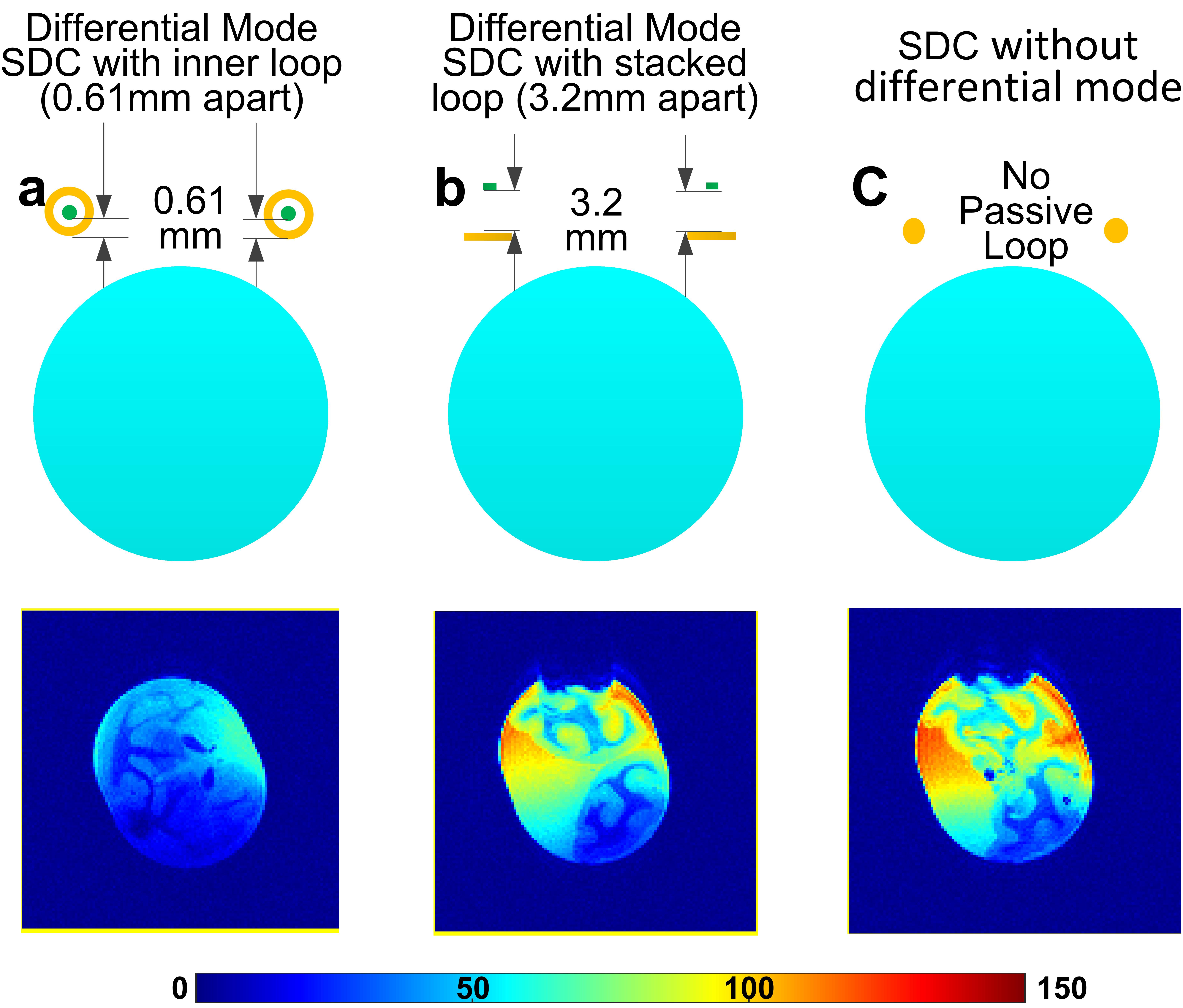
Figure 5 Axial SNR maps on an ex-vivo squirrel monkey brain with an unoptimized differential-mode self-decoupled coil (SDC) (a), an optimized differential-mode SDC (b) and a conventional SDC (c). The unoptimized coil was built from a semi-rigid coax with 0.6 mm distance between the inner and outer conductor. The optimized coil is built from copper tapes on both sides of a 3.2-mm-thick Teflon board. The conventional SDC was built from 14-gauge copper wires. SNR maps were calculated based on GRE images (FA=35o, TR/TE=480/10ms. FOV=64x64mm2; Matrix=128x128; slice thickness=0.5mm).