4066
Dual Band Lattice Balun for Multinuclear MRI1Biomedical Engineering, Vanderbilt University, Nashville, TN, United States, 2Vanderbilt University Institute of Imaging Science, Vanderbilt University, Nashville, TN, United States, 3Radiology, Vanderbilt University, Nashville, TN, United States, 4Electrical and Computer Engineering, Vanderbilt University, Nashville, TN, United States
Synopsis
Baluns are transformers commonly used to connect RF coils to coaxial cables. For dual-tuned RF coils, baluns suppress the common-mode current at the Larmor frequencies for both proton and X-nuclear. This can be realized by utilizing separated single-frequency baluns in series or utilizing dual-band baluns. The LC lattice balun is widely used in RF coils since it can be built directly on the coils’ feeding board and uses minimal space. In this work, we introduce a dual-band Lattice balun design to fit the multinuclear MRI application. We analyzed, simulated and constructed the dual-band lattice balun for the 7T H/Na application.
Purpose
Baluns, standing for balanced to unbalanced transformers, are commonly used to connect an RF coil (a balanced device) to a coaxial cable (an unbalanced device). For dual-tuned RF coils, baluns are required to suppress common-mode currents at both proton and X-nuclear Larmor frequencies. This can be realized using separate single-frequency baluns in series, or dual-band baluns based on a cable trap design [1]. The LC lattice balun [2,3] is also widely used with RF coils because it can be built directly on the coils’ feed board and has a minimal footprint. In this work, we introduce a dual-band Lattice balun design for multinuclear MRI [4]. We analyzed, simulated and constructed the circuit for 7T proton and sodium imaging.Methods
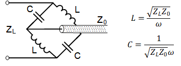
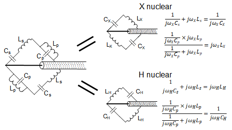
Theory:Fig.1 shows a schematic of a single-band 90-degree lattice balun. The two branches have +90 and -90 phase shifts, respectively. Therefore, the total phase difference between the branches’ terminals is 180 degrees and is balanced. The values of the lumped capacitors and inductors can be derived using quarter wavelength equations, as shown in the figure. To achieve a dual-band design, we replace each capacitor or inductor with a parallel or series LC circuit, respectively, that exhibits different impedances at frequencies higher than f0 (the LC circuit’s self-resonant frequency) and at frequencies lower than f0. A parallel LC circuit acts as a capacitor for f > f0 and an inductor for f < f0, while a series LC circuit acts as an inductor for f > f0 and a capacitor for f < f0. If the values of the capacitors and inductors are chosen to meet the equations in Fig. 2, the dual-band circuit acts as a +90/-90 Lattice balun at the X-nuclear Larmor frequency and a -90/+90 Lattice balun at the proton Larmor frequency.
Simulations:
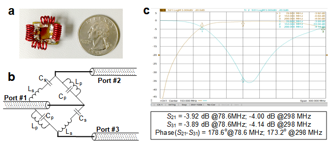
A dual-band Lattice balun circuit for 7T proton and sodium imaging (Larmor frequencies are 298 MHz and 78.6 MHz, respectively) was simulated using the Ansys EM package (Canonsburg, PA, USA), as shown in Fig. 3. The capacitance and inductance were calculated from the equations in Fig. 2 (Ls = 36.27 nH, Cs = 29.82 pF, Lp = 74.54 nH, Cp = 14.51 pF), as shown in Fig. 3a. For simplicity, ideal components without series resistances or parasitic capacitances/inductances were used. Note that this is a 50-to-50 ohm balun, so the impedance of each balanced terminal should be 25 ohms to get perfect S21/S31 (-3dB, +-90 degree) values. To guide the real circuit construction and testing, we also simulated the S21/S31 with all ports set to 50 ohms, which is much easier to calibrate in practice.
Fabrication and Evaluation:
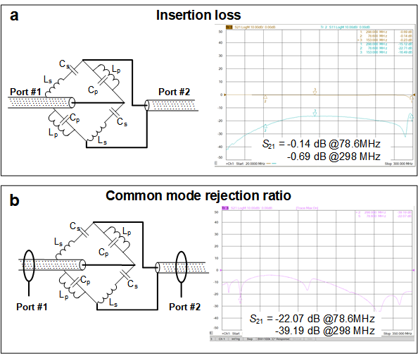
The 7T H/Na dual-band Lattice balun was built (Fig.4a) with high-Q ceramic capacitors (PPI, 1111C series) and hand-wound inductors. It is highly-miniaturized, with a size of 1.25x1.27cm2. The impedance balance/imbalance performance was evaluated on the bench with a calibrated network analyzer. The insertion loss of the circuit’s differential mode was measured as the S21 between the unbalanced terminal and the balanced terminal. The circuit’s common-mode rejection capability was measured with two current probes electromagnetically coupled to the input and output coax shields [5]. One current probe transmits current onto the input coax’s shielding, whereas the other probe measures the attenuation of this current on the output coax’s shielding (evaluated by S21).
Results and Discussion
As expected, the circuit simulation showed that the two balanced terminals had equal magnitude (both -3 dB) and were out of phase (+90 and -90) at both frequencies, which is consistent with the theoretical analysis. We also found that the difference between 25-ohm and the 50-ohm setting was only that the S21/S31 magnitude decreased simultaneously by 0.52 dB. Therefore, there was no need to re-calibrate the VNA to 25 ohms. Fig. 4 shows the dual-band balun for H/Na imaging at 7T, with magnitude/phase difference of 0.03 dB/178.6 degrees at 78.6 MHz and 0.14 dB/173.2 degrees at 298 MHz. Fig. 5 show its insertion loss, with 0.14/0.69 dB at 78.6/298 MHz, and common-mode rejection ratios, with up to 22/39 dB at 78.6/298MHz.Compared to building single-band Lattice balun with 4 lumped elements, it seems more challenging to build a dual-band balun with 8 lumped elements. However, the following findings support its reproducibility: (1) The performance of high and low frequencies are determined separately: the high frequency is determined by Ls and Cp, while the low frequency is determined by Lp and Cs; (2) The Lp and Cs that determine the low frequency response do not need to be tuned since the parasitic capacitance/inductance is negligible at low frequencies. The actual value of Cp can be predicted, and mainly Ls needs to be adjusted, which can be easily realized by varying the distance between turns. This balun was fabricated on an FR4 board, and we expect its insertion loss, especially the loss at the high frequency, will be further reduced using lower loss substrates such as PTFE and Rogers materials.
Conclusion
We introduce a dual-band Lattice balun for multinuclear MRI applications. This dual band balun is miniaturized and can be integrated into a coil’s feed board and has high common-mode rejection ratio and low insertion loss.Acknowledgements
This work was supported by NIH R01 EB 016695 and U01 EB 025162.References
1. Dabirzadeh A, McDougall MP. Trap design for insertable second-nuclei radiofrequency coils for magnetic resonance imaging and spectroscopy. Conc Magn Reson B. 2009;35B:121–132
2. C.LORENZ AG Berlin-Tempelhof, “Schaltungsanordnunk zum Ubergang von einer symmetrischen, lektrischen Anordnung zu einer unsymmetrischen, insbesondere bei Hochfrequenzanwendungen,” German Patent, , no. 603816, April 1932
3. Holcomb WG and Gore JC. “An improved network for impedance matching and simultaneous unbalanced to balanced transformation.” Magn. Reson. Imag. 3, 295-296 (1985)
4. Sung, J. H., Kim, G. Y., Son, S. H., Lee, H. J., Song, Y. J., Jeong, Y. W., ... & Ahn, D. (2002, June). Design method of a dual band balun and divider. In 2002 IEEE MTT-S International Microwave Symposium Digest (Cat. No. 02CH37278) (Vol. 2, pp. 1177-1180). IEEE.
5. Peterson, D. M., Beck, B. L., Duensing, G. R., & Fitzsimmons, J. R. (2003). Common mode signal rejection methods for MRI: reduction of cable shield currents for high static magnetic field systems. Concepts in Magnetic Resonance Part B: Magnetic Resonance Engineering: An Educational Journal, 19(1), 1-8.
Figures