4065
A custom-made design for integrating a magnetic field monitoring system into a 32ch MRI head coil1Laboratory for Social and Neural Systems Research (SNS lab), University of Zurich, Zurich, Switzerland
Synopsis
While magnetic field probes can concurrently measure the spatio-temporal magnetic field dynamics during the acquisition of spiral or EPI readout, incorporating such field probes into a head coil requires careful planning and execution. The final set-up must conform to a wide array of boundary conditions for a safe and easy-to-use installation. The specific aims of this project were installing magnetic field probes into a Siemens 32ch coil and make that set-up compatible with a 3T Philips Achieva scanner. It was a high risk/gain project that was achievable only with a widely interdisciplinary approach and the kind input of colleagues.
Introduction
Magnetic field monitoring1,2 uses a set of 16 field probes3 that concurrently measure the spatio-temporal magnetic field dynamics during the acquisition of spiral4 or echo planar imaging (EPI)5 data in diffusion6,7 or funcational8,9 MRI experiments. These additional data are used in an offline reconstruction to correct for artifacts that otherwise would result from readout trajectory deviations. Incorporating such field probes into the MR environment requires careful planning and execution8,10. The design must conform to a wide array of boundary conditions that demand a safe and easy-to-use installation while simultaneously maintaining the high MRI data quality.The specific aims of this project were installing magnetic field probes into a Siemens 32ch coil and make it compatible with a 3T Philips Achieva scanner.
Methods
The design and assembly proceeded iteratively over several phases. Temporal SNR (tSNR) and a B1+ map11,12 were collected throughout as quality assurance measures. tSNR was calculated from an fMRI time-series, voxel size = 3.0x3.0x3.0mm3, TR/TE = 2800/30ms for 3T Philips Achieva (Best, The Netherlands) scanner and voxel size = 3.0x3.0x2.5mm3, TR/TE = 3430/30ms for Siemens Trio (Erlangen, Germany) scanner. The actual flip angle imaging (AFI) B1+ map had TR1/TR2 = 46/138ms, TE = 2.2ms, nominal flip angle=60°, spoiler gradient moments for TR1/TR2=931.8/1971.0 mT×ms/m12, RF spoiling phase increment=39°. The FID lifetime of the probes was evaluated before and after installation.Phase_1: We collected tSNR and B1+ data with the 32ch Siemens head coil in a 3T Siemens Trio scanner. These data were used as a gold standard, against which to compare later phases. Analogous tSNR and B1+ mapping data were collected with the Philips 8ch and 32ch coils without magnetic field probes installed within. Thus they served as an unbiased standard to compare the custom coil. An additional B1+ map was acquired with the Philips 8ch coil integrated with the 16 field probes.
Phase_2: The coil was made compatible with our 3T Philips Achieva scanner by Rapid (Rimpar, Germany). tSNR and B1+ data were collected.
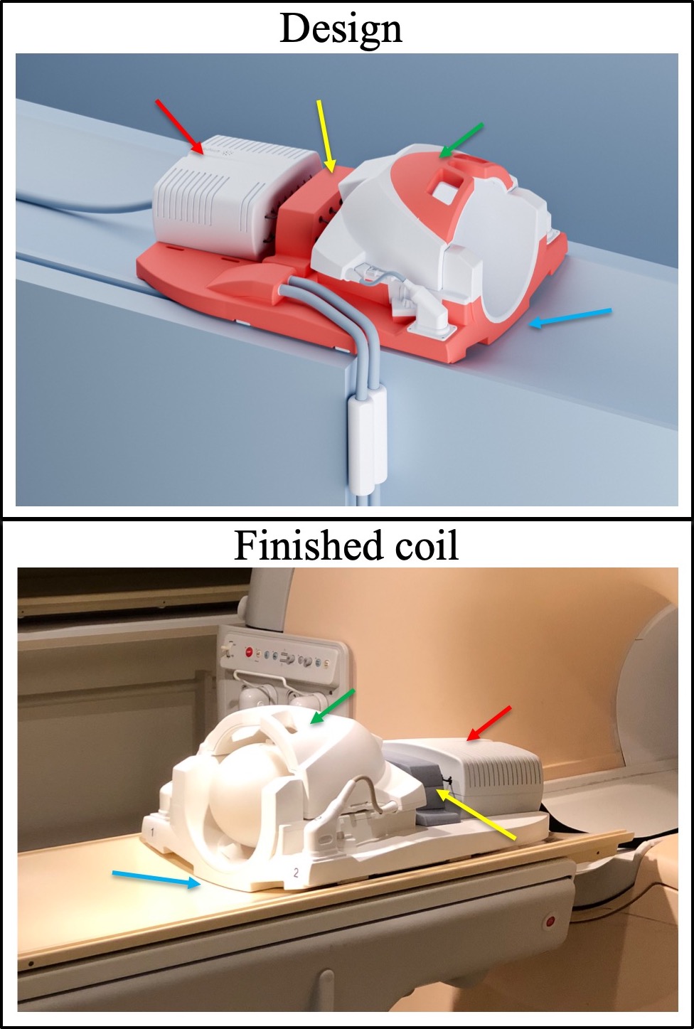
Phase_3: The magnetic field probes (Skope, Zurich, Switzerland) were first installed into the coil in this phase with the help of an adapted design of the plastic housing (Fig_1) that fuses parts of the digital 3D models of the 32ch Philips and Siemens coils and proceeded in Fusion 360 (Autodesk) CAD software. The modified parts of the design were 3D printed and assembled with the original housing of the 32ch Siemens coil. The first version of the design a) made the Siemens coil compatible with the Philips bed, b) houses the probes under the plastic covers to minimize distance but avoid direct contact to volunteer, c) conveniently accommodates additional hardware and d) minimizes cable lengths. tSNR and B1+ data were collected before installation of RF cable traps.
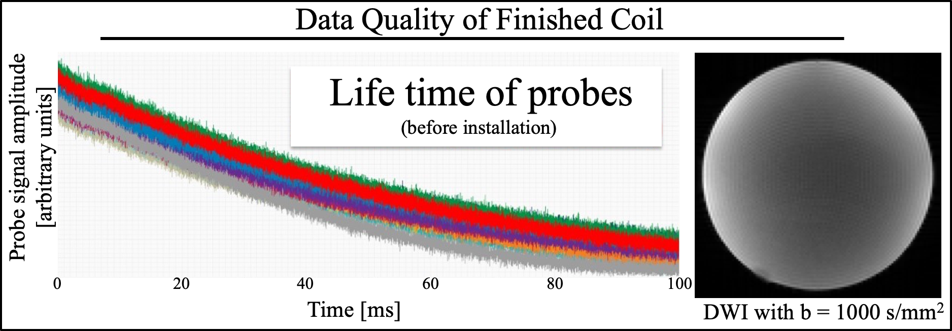
Phase_4: The housing was modified to also conveniently incorporate RF cable traps. tSNR and B1+ data were acquired. To test the final set up, a diffusion imaging dataset were collected on a spherical silicon oil phantom with isotropic resolution of 1.7mm, 64 diffusion-weighted images (b=1000 s/mm^2) and a reference image. The offline reconstruction combined the 32ch MRI raw data with the magnetic field monitoring data as in Wilm et al.6,13,14.
Results
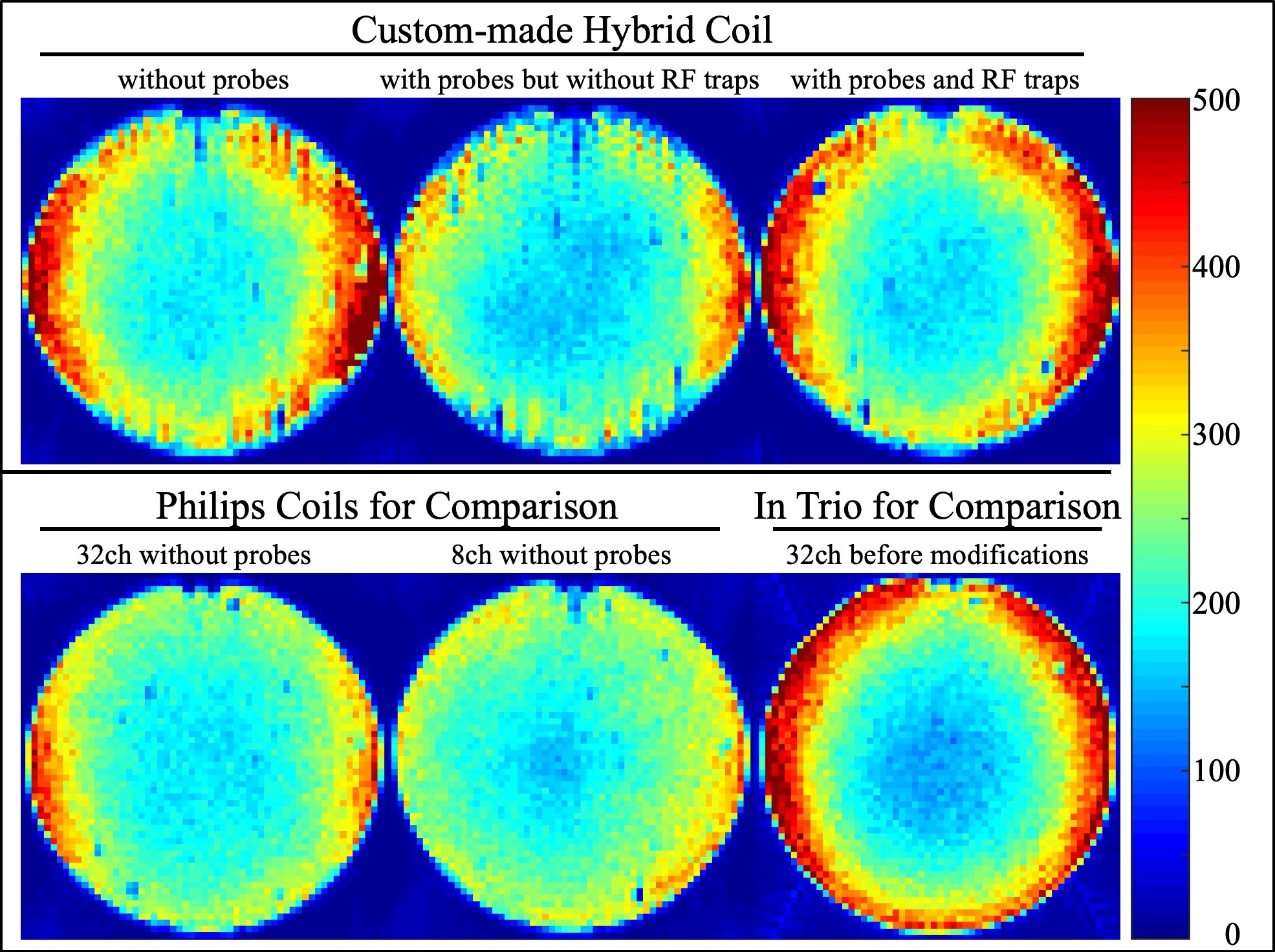
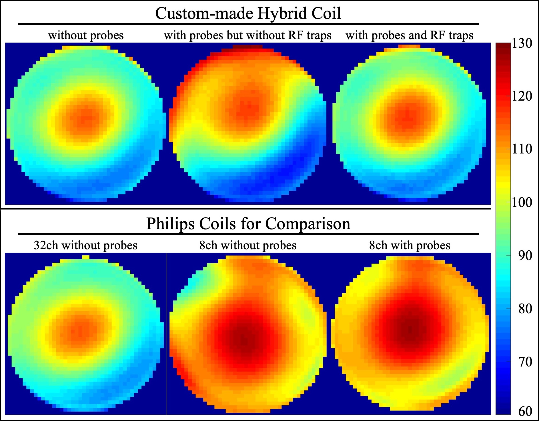
The redesigned plastic housing of the coil compliments the shape of the patient bed, accommodates the RF traps and auxiliary electronics, ensures minimal cable lengths, inhibits direct contact between probes and human volunteers and generally provides a durable and easy-to-handle solution. The tSNR (Fig_2) and B1+ (Fig_3) data ascertain that installation maintains high MRI data quality and importantly the custom coil outperforms the other 8ch and 32ch coils. The slight reduction in tSNR and the slight deviation in B1+ maps was expected from the RF shielding effect the probes and necessary cabling. It is remarkable that as opposed to installing such probes into the 8ch coil, RF traps on every probe cable proved necessary for the 32ch coil. The FID lifetime of the 16 magnetic field probes are shown in Fig_4. After installation 90% of FID lifetime was preserved.The slightly shorter FID lifetimes were expected given local Bo field distortions caused by coil hardware and plastic housing in the local proximity of the probes. Fig_4 also provides a slice of the diffusion imaging data set that was reconstructed with the input of the additional field monitoring data.Discussion
We achieved an installation of magnetic field probes into a 32ch head coil with minimal loss in MRI data quality. This ensures not only that standard operating procedures can proceed unaffected but indeed provided an unprecedented data quality – compared to the other available coils from the native vendor. The final solution required specialized industrial design skills that helped ensure a durable, safe, easy-to-handle/maintain, cost effective and aesthetically pleasing coil. The improved tSNR compared to the 8ch coil is not surprising. The difference in tSNR between the two 32ch coils is simply a result of application criteria. The 32ch Philips coil is optimized for clinical scanning and hence has a larger diameter, accommodates a larger % of the population and is arguably more comfortable, while the 32ch Siemens coil is aimed at neuroscientific experiments.Acknowledgements
This work was supported by Swiss National Science Foundation (grant nrs:316030_164076 & 31003A_166118). The authors gratefully acknowledge the assistance of colleagues within Skope Magnetic Resonance Technologies, Rapid Biomedical, Philips Healthcare and the Siemens Healthineers team. Many thanks also to Dr. Frédéric Grouiller from the Brain and Behavior Laboratory at the University of Geneva for help with testing the 32ch coil in a Siemens Trio scanner in the initial phase of this project.References
1. Barmet, C., De Zanche, N. & Pruessmann, K. P. Spatiotemporal magnetic field monitoring for MR. Magn Reson Med 60, 187–197 (2008).
2. Dietrich, B. E. et al. A field camera for MR sequence monitoring and system analysis. Magn Reson Med (2015). doi:10.1002/mrm.25770
3. De Zanche, N., Barmet, C., Nordmeyer-Massner, J. A. & Pruessmann, K. P. NMR Probes for measuring magnetic fields and field dynamics in MR systems. Magn. Reson. Med. 60, 176–186 (2008).
4. Glover, G. H. Spiral imaging in fMRI. Neuroimage 62, 706–712 (2012).
5. Schmitt, F. et al. Echo-Planar Imaging: Theory, Technique and Application. (Springer, 1998).
6. Wilm, B. J. et al. Diffusion MRI with concurrent magnetic field monitoring. Magn Reson Med74, 925–933 (2015).
7. Wilm, B. J. et al. Single-shot spiral imaging enabled by an expanded encoding model: Demonstration in diffusion MRI. Magn Reson Med 77, 83–91 (2017).
8. Engel, M. et al.Single-shot spiral imaging at 7 T. Magn. Reson. Med. 80, 1836–1846 (2018).
9. Bollmann, S. et al. Analysis and correction of field fluctuations in fMRI data using field monitoring. Neuroimage 154, 92–105 (2017).
10. Kennedy, M., Lee, Y. & Nagy, Z. An industrial design solution for integrating NMR magnetic field sensors into an MRI scanner. Magn Reson Med 80, 833–839 (2018).
11. Yarnykh, V. L. Optimal radiofrequency and gradient spoiling for improved accuracy of T1 and B1 measurements using fast steady-state techniques. Magn Reson Med 63, 1610–1626 (2010).
12. Lee, Y. J., Callaghan, M. F. & Nagy, Z. Analysis of the Precision of Variable Flip Angle T1 Mapping with Emphasis on the Noise Propagated from RF Transmit Field Maps. Front. Neurosci. 11, (2017).
13. Wilm, B. J., Barmet, C., Pavan, M. & Pruessmann, K. P. Higher order reconstruction for MRI in the presence of spatiotemporal field perturbations. Magn Reson Med 65, 1690–1701 (2011).
14. Wilm, B. J., Barmet, C. & Pruessmann, K. P. Fast higher-order MR image reconstruction using singular-vector separation. IEEE Trans Med Imaging 31, 1396–1403 (2012).
Figures