4064
Multi-loop radio frequency coil elements1Division MR Physics, Center for Medical Physics and Biomedical Engineering, Medical University of Vienna, Vienna, Austria, 2IR4M (Imagerie par Résonance Magnétique et Multi-Modalités), UMR 8081, Université Paris-Sud/CNRS, Université Paris-Saclay, Orsay, France
Synopsis
FDTD simulations and experimental B1 mapping at 3T and 7T demonstrate that multi-loop coils (MLCs), i.e. coils made of small loops in series, provide a significant transmit efficiency boost over conventional loop coils at close distance in sample noise dominated settings. Further away, the performance of MLCs is comparable to single loop coils. The MLC principle brings additional degrees of freedom for coil design and optimization and appears advantageous for single coils as well as individual elements of arrays, especially for applications with large target area and shallow target depth, e.g. skin imaging or high resolution MRI of brain slices.
Introduction
The development of high-density RF coil arrays gives rise to several challenges due to increased complexity with respect to mutual decoupling and electronic circuitry required for interfacing and signal conditioning. Here, we investigate an alternative strategy, based on single coil elements composed of small loops in series, referred to as “multi-loop coils (MLCs)”. This study complements other works investigating small loops associated to larger coils1-5.Methods
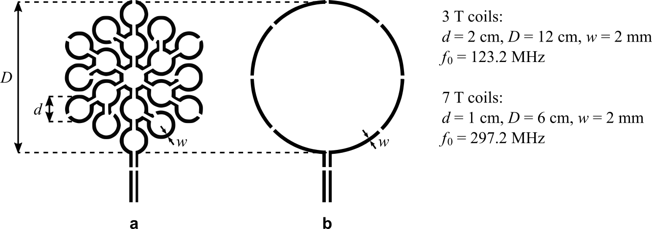
In sample noise dominated settings, the achievable SNR is limited by sample-induced noise. The use of small loops in series appears particularly advantageous for reducing sample-induced noise which varies with the loop radius to the power of three6, while the equivalent noise voltages induced in each loop are summed linearly as they are in series. The MLC principle may also improve the magnetic coupling to the sample because the magnitude of the detected MR signal is inversely proportional to the loop radius at close distance7.We evaluate this potential sensitivity improvement by investigating two MLCs made of 19 equal loops in series at 3T and 7T. Each MLC is compared to a single loop coil (SLC) with equal outer diameter (see Figure 1). Coil diameters were chosen to achieve sample noise dominance. All coils were fabricated from single-layer copper-clad (35 µm) FR4 substrate (0.8 mm) by standard photolithographic processing.
MLCs and SLCs were compared by FDTD simulations (XFdtd 7.8, Remcom, USA) with circuit co-simulation8,9 (ADS, Keysight Technologies, USA) in terms of transmit efficiency, i.e. B1+/√Pin, and 10g-averaged SAR. A box-shaped phantom was used as load (3T: 170 mm x 170 mm x 150 mm; 7T: 90 mm x 90 mm x 70 mm, σ = 0.71 S/m, ε = 63.86). Post-processing was done using an in-house Matlab toolbox (SimOpTx, MedUni Vienna, AUT) employing the quadratic form power correlation matrix formalism10,11.
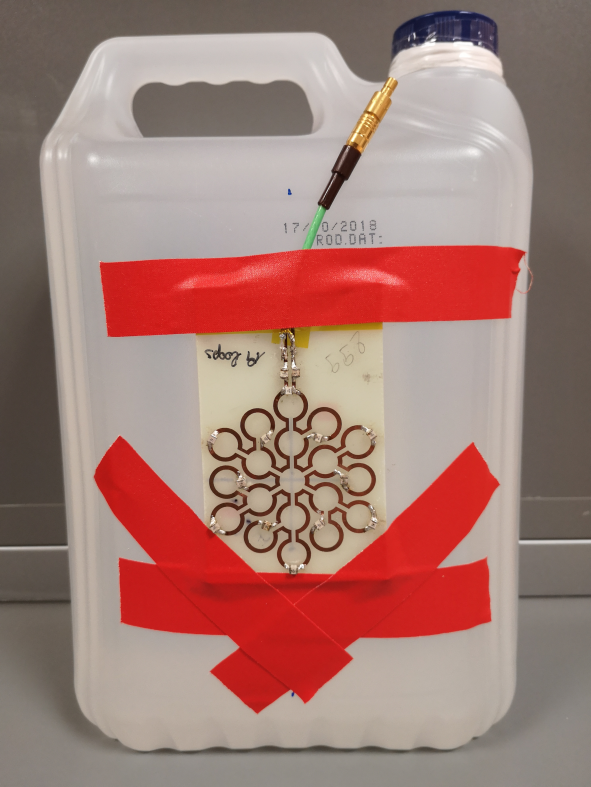
On the bench, loaded and unloaded Q-factors of all investigated coils were measured. MR experiments (3T Prisma Fit, Magnetom 7T MRI; Siemens, GER) were carried out with all coils in transmit-receive mode. Home built (3T) and third party (7T; Stark Contrast, GER) transmit-receive switches with integrated low-noise preamplifiers (3T: 0.5 dB noise figure, 27.0 ± 0.1 dB gain, Hi-Q.A. Inc., CAN; 7T: 0.5 dB noise figure, 27.2 ± 0.2 dB gain, Siemens, GER) were used. The phantom for experiments with the 7T MLC attached to it is shown in Figure 2.
Flip angle maps in slices orthogonal to the coil axis were acquired (3 mm thickness, 2 mm spacing) using the saturated Turbo FLASH method12 adapting the saturation pulse amplitude for different slices to counterbalance the B1 decrease. From flip angle data, transmit efficiency maps were calculated accounting for an insertion loss of -2 dB of coil cables and T/R-switches.
Results
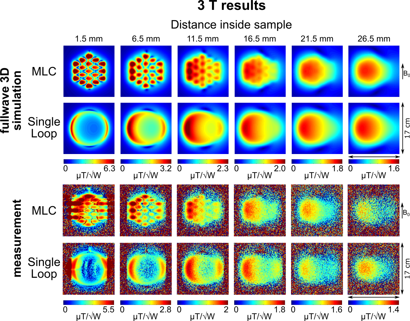
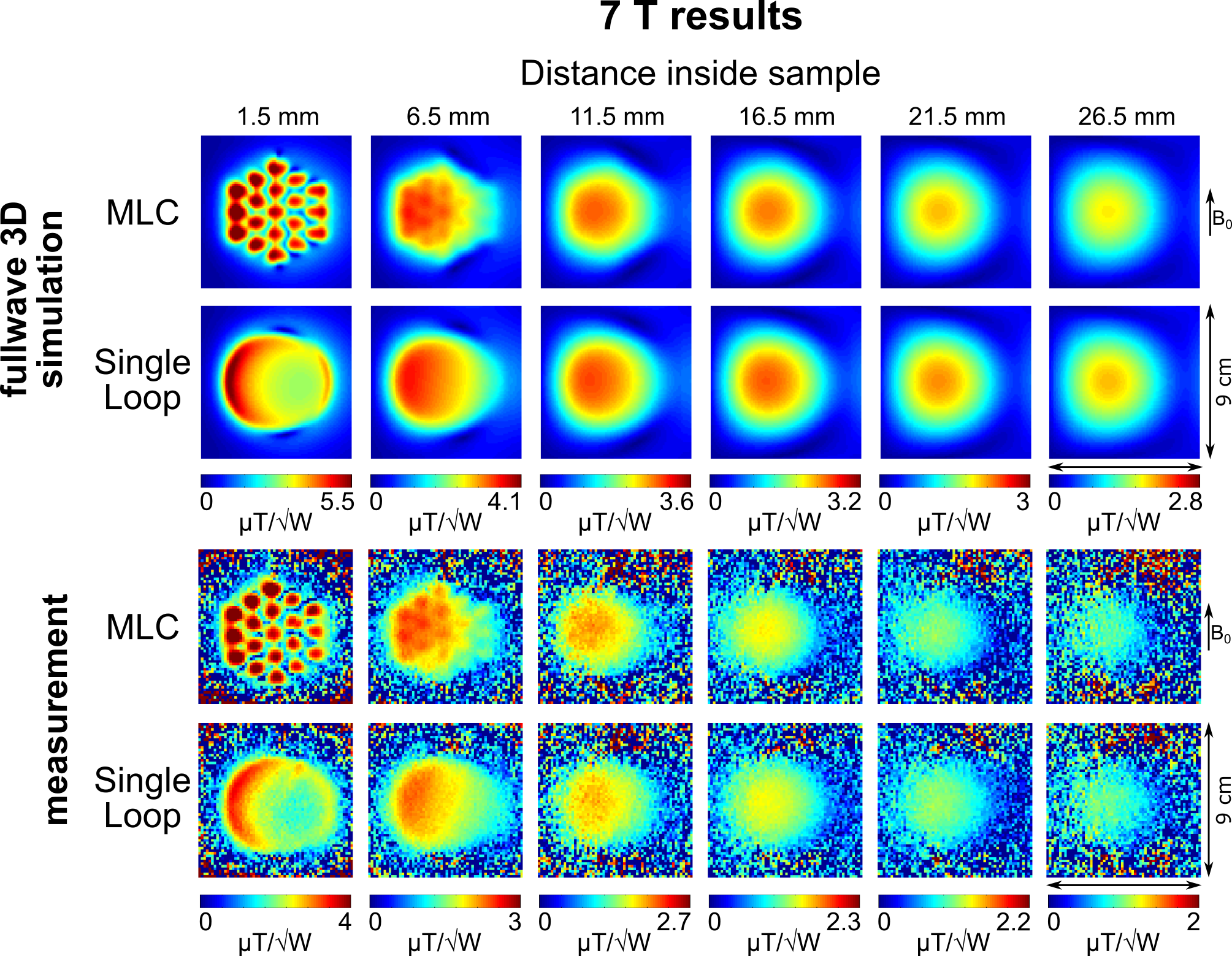
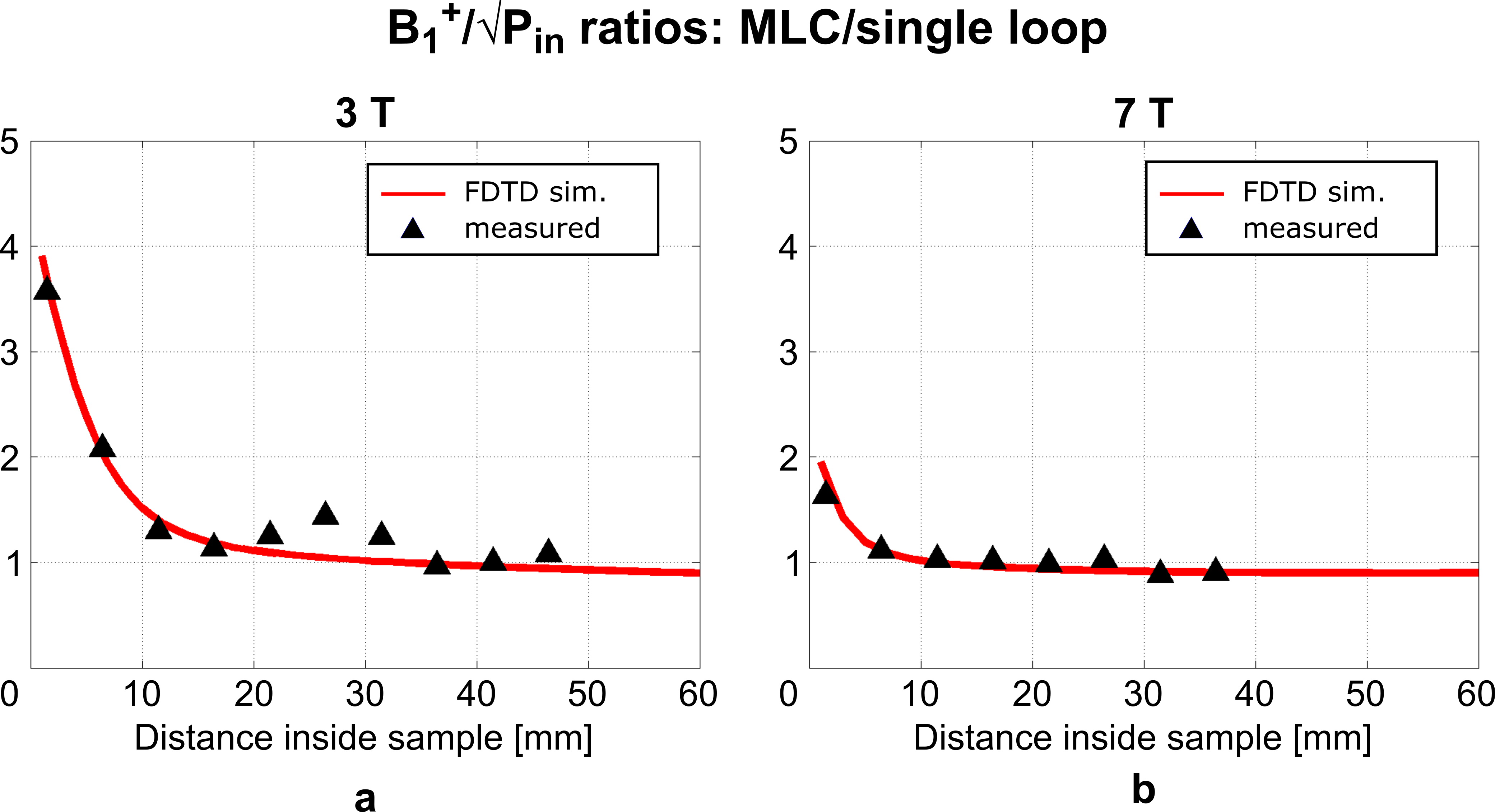
Unloaded Q-factors are lower for MLCs (3T: 163, 7T: 176) than for SLCs (3T: 203, 7T: 268). However, overall, sample noise clearly dominates. Loaded Q-factors are higher for MLCs (3T: 33, 7T: 30) than for SLCs (3T: 9, 7T: 7.2) by factors of 3.67 and 4.17 at 3T and at 7T, respectively, demonstrating the sample noise reduction by the MLC principle.Simulated and measured transmit efficiency maps are summarized in Figures 3 and 4 for 3T and 7T, respectively. Transmit efficiency ratios between MLCs and SLCs along the central coil axis are shown in Figure 5. Excellent qualitative agreement between simulations and measurements is observed for 3T and 7T. A maximum increase in transmit efficiency by a factor between 2 and 4 depending on field strength and coil size is obtained with MLCs compared to SLCs. A significant gain is found for distances up to the diameter d of the individual MLC loops, i.e. 2 cm for 3T and 1 cm for 7T. For larger distances, the performance of MLCs and SLCs is comparable. Quantitatively, experimental values are approximately 15% and 25% lower than simulated values for 3T and 7T, respectively. Potential explanations are a mismatch in sample conductivity between experiment and simulation or an underestimation of losses in simulation either in the coil or interface components.
Maximum 10g-averaged SAR was found to be slightly lower for MLCs in comparison to SLCs, with differences of -9.7% and -16.3% at 3T and 7T, respectively.
Discussion and Conclusion
MLCs exploit the high sensitivity of small surface coils providing strong magnetic coupling to the sample while reducing sample-induced noise together with an extended FoV. As compared to SLC arrays, the MLC principle brings simplicity for design and fabrication, while aiming at comparable sensitivity. However, using a single MLC instead of an SLCs array is not compatible with parallel imaging techniques.Results obtained here can be assumed to be representative for the general sensitivity improvement potentially achieve with the MLC principle. Depending on operating frequency and desired FoV, different number, size and shape of loops may be advantageous.
Several applications may well benefit from MLCs, primarily used as single coils when high sensitivity over a FoV that is large compared to the target depth is required, e.g. skin imaging13, or ex vivo imaging of brain slices14. In addition, MLCs can also be employed as building blocks of arrays for even larger FoVs, which is subject to future studies.
Acknowledgements
This work was funded by the Austrian/French OeAD WTZ grant FR 03/2018, and the Austrian Science Fund grant FWF P28059.References
1. Mansfield P. The petal resonator: a new approach to surface coil design for NMR imaging and spectroscopy. J Phys D Appl Phys. 1988; 21:1643–1644. doi:10.1088/0022-3727/21/11/015
2. Rodriguez AO, Hidalgo SS, Rojas R, Barrios FA. Experimental development of a petal resonator surface coil. Magn Reson Imaging. 2005; 23:1027–1033. doi:10.1016/j.mri.2005.09.001
3. Dona Lemus OM, Konyer NB, Noseworthy MD. Micro-strip Surface Coils Using Fractal Geometry for 129Xe Lung Imaging Applications. ISMRM. 2018; 1713.
4. Solis S, Vazquez F, Martin R, Lazovic J, Marrufo O, Medina L, Rodriguez A. Bio-inspired surface coil for preclinical MRI at 15.2 T. ESMRMB. 2019; P02.18
5. Nowikow C, Konyer N, Yazdanbakhsh P, Noseworthy MD. Koch Snowflake Fractal RF Surface Coils to Improve 23Na-Magnetic Resonance Imaging at 3T. ESMRMB. 2019; P02.14
6. Suits BH, Garroway AN, Miller JB. Surface and gradiometer coils near a conducting body: the lift-off effect. J Magn Reson. 1998; 135:373–9. doi:10.1006/jmre.1998.1608
7. Simpson J, Lane J, Immer C, Youngquist R. Simple Analytic Expressions for the Magnetic Field of a Circular Current Loop. 2001; https://ntrs.nasa.gov/archive/nasa/casi.ntrs.nasa.gov/20010038494.pdf
8. Kozlov M, Turner R. Fast MRI coil analysis based on 3-D electromagnetic and RF circuit co-simulation. J Magn Reson. 2009; 200:147–152. doi:10.1016/j.jmr.2009.06.005
9. Lemdiasov RA, Obi AA, Ludwig R. A numerical postprocessing procedure for analyzing radio frequency MRI coils. Concepts Magn Reson Part A. 2011; 38A:133–147. doi:10.1002/cmr.a.20217
10. Graesslin I, Homann H, Biederer S, Börnert P, Nehrke K, Vernickel P, Mens G, Harvey P, Katscher U. A specific absorption rate prediction concept for parallel transmission MR. Magn Reson Med. 2012; 68:1664–74. doi:10.1002/mrm.24138
11. Kuehne A, Goluch S, Waxmann P, Seifert F, Ittermann B, Moser E, Laistler E. Power balance and loss mechanism analysis in RF transmit coil arrays. Magn Reson Med. 2015; 74:1165–1176. doi:10.1002/mrm.25493
12. Chung S, Kim D, Breton E, Axel L. Rapid B1+ mapping using a preconditioning RF pulse with TurboFLASH readout. Magn Reson Med. 2010; 64:439–446. doi:10.1002/mrm.22423
13. Laistler E, Loewe R, Moser E. Magnetic resonance microimaging of human skin vasculature in vivo at 3 Tesla. Magn Reson Med. 2011; 65:1718–23. doi:10.1002/mrm.22743
14. Gruber B, Keil B, Witzel T, Nummenmaa A, Wald LL. A 60-Channel Ex-Vivo Brain-Slice Coil Array for 3T Imaging. ISMRM. 2014; 4885.
Figures