4063
Saddle Coil Design for MRI/MRS at 14.1 Tesla: A Favorable Alternative to the Quadrature Birdcage Coil
Claudia Christina Zanella1, Jérémie Daniel Clément1,2, Daniel Wenz3, Bernard Lanz1, and Rolf Gruetter1
1Laboratory for Functional and Metabolic Imaging (LIFMET), EPFL, Lausanne, Switzerland, 2School of Biomedical Engineering and Imaging, King's College London, London, United Kingdom, 3Center for Biomedical Imaging – Animal and Imaging Technology (CIBM-AIT), EPFL, Lausanne, Switzerland
1Laboratory for Functional and Metabolic Imaging (LIFMET), EPFL, Lausanne, Switzerland, 2School of Biomedical Engineering and Imaging, King's College London, London, United Kingdom, 3Center for Biomedical Imaging – Animal and Imaging Technology (CIBM-AIT), EPFL, Lausanne, Switzerland
Synopsis
A single channel 1H saddle coil and a quadrature 1H 8-leg birdcage coil were compared in terms of $$$B_1^+$$$ homogeneity and $$$B_1^+$$$ efficiency for preclinical small-animal imaging at 14.1 Tesla. Electromagnetic field simulations showed that the saddle coil generated a more homogeneous $$$B_1^+$$$ field for all regions of interest (up to 13.7 mm central disk diameter) than the birdcage coil. Saline phantom measurements showed a more constant flip angle excitation upon multi-slice imaging in axial direction and a 66% higher $$$B_1^+$$$ efficiency for the saddle coil.
Introduction
Many applications in MRI rely on high transmit field ($$$B_1^+$$$) homogeneity. Simultaneously, it is advantageous to maintain high $$$B_1^+$$$ efficiency and receive sensitivity. To insure $$$ B_1^+ $$$ homogeneity, volume coils are preferred to surface coils. For preclinical research, thus small regions of interest (ROI), Birdcage Coils (BC) and saddle coils are popular design choices1. However, BC used at ultra-high field such as 14.1T have to deal with rather small diameters due to the reduced bore size, which entails distorted $$$B_1^+$$$ homogeneity2,3. Previous work showed that a single channel saddle coil yielded higher sensitivity than a quadrature BC for an object of the size of a rat upper thigh4. In the present work, we investigated how saddle coil and BC perform at 14.1T in terms of $$$B_1^+$$$ homogeneity and $$$B_1^+$$$ efficiency. Quantitative analysis was done via electromagnetic field simulations and phantom measurements.Methods
Both coils were designed to accommodate a rat head or thigh and to fit the 14.1T magnet bore, with coil diameter ø=50.6mm, length $$$l$$$=27mm for the shielded 8-leg 1H quadrature BC and ø=34mm, $$$l$$$=22mm for the unshielded saddle coil (more compact due to its more open design)4. The saddle coil angular aperture α=120° was adjusted to minimize radially dependent contributions to the central magnetic field5. The electromagnetic field simulations were performed using finite-difference time-domain model based software Sim4Life4.0.1 (ZMT,Switzerland).Flip angle (θ) maps of a saline phantom were acquired via gradient echo imaging (Gaussian pulses of τ=2ms duration, TR/TE=20000/4.83ms, θ=60°/120°, matrix size =128x128, FOV=25x25mm2) and calculated according to the double angle method, θ=cos-1(I2 /2I1)6,7 with voxel-wise magnitude image intensity I. $$$B_1^+$$$ homogeneity was quantified over a ROI of 11mm diameter (ROIø11) using: (1) Non-Uniformity (NU) (=$$$\sigma(B_1^+)/\overline{B_1^+}$$$) and (2) Relative Uniformity (RU) (percentile number of voxels which deviate by $$$\leq$$$10% from $$$\overline{B_1^+}$$$)8. The calibration power was determined for localized (11.2x11.2x3mm3 voxel) acquisition using asymmetric 90° stimulated echo acquisition mode pulses (width $$$\tau$$$=500s, TE=2.8ms)9,10. Resonance modes and quality factors (Q) were measured on a network analyzer11.
Results
Fig.1 displays scattering parameters and respective resonance modes. The saddle coil has a single resonance at 600MHz contrarily to the BC which has a number of modes. Transmit field simulations are shown in Fig.2. Homogeneity over axial slices spanning a 14mm region were non-uniformity NU*=1.0$$$\pm$$$0.1% and NU=2.7$$$\pm$$$0.1% for saddle coil and BC, respectively. For ROIø11 we found NU*=1.7%, RU*=100% for the saddle coil and NU=4.0%, RU=95.4% for the BC on the axially central slice. The flip-angle dependency on the axial slice position showed a constant increase from $$$\alpha\vert$$$z=-6mm=20.4$$$\pm$$$1.0° to $$$\alpha\vert$$$z=+6mm =33.6$$$\pm$$$1.1° in an 11mm diameter central ROI (147 voxel) for the BC (Fig.3). The saddle coil created constant nominal flip angles over the first 4 slices in direction of the source with $$$\bar{\alpha}\vert$$$-6<z<0mm=30.2$$$\pm$$$0.6° and only then gradually decreased to $$$\alpha\vert$$$z=+6mm=19.0$$$\pm$$$2.4°. Fig.4 shows the transmit field in phantoms where NU*=5.0%, RU*=91.1% for the saddle coil and NU=3.5%, RU=97.7% for the BC.The saddle coil needed 5-6dB less power to create a 90° pulse upon localized acquisition. $$$B_1^+$$$ efficiency was estimated to be 8.8$$$\pm$$$0.6$$$\mu T/\sqrt{kW}$$$ for saddle coil and 5.3$$$\pm$$$0.2$$$\mu T/\sqrt{kW}$$$ for BC. Table1 contains unloaded (Qul) and loaded (Ql) quality factors with Qul/Ql=2.7 and Qul/Ql=1.1 for saddle coil and BC, respectively.
Discussion
Electromagnetic field simulations showed the saddle coil to outperform the BC in terms of transmit field homogeneity over (a) slices in axial direction and (b) over ROIs with different diameters in the axially central slice. The same pattern of slight $$$B_1^+$$$ inhomogeneity derived from simulations was also observed in phantom measurements (diagonal under-intensity shades in figures 2A,B and 4A,B), supporting the validity of the simulations results. Inaccuracies between the simulations and measurements arise from imperfections in angular symmetry, non-ideal current distribution throughout the rungs, RF losses and balanced segmenting capacitors. On the practical side, tuning and matching is not trivial for BC due to coupling between the two channels, multi-modal resonance spectra and potential splitting of degenerate modes. It is all the more straightforward in the case of a single-resonance saddle coil. The ratio Qul/Ql=1.1 for the BC was confirmed in previous publications12. Due to the lower number of RF components on the saddle coil, less power is dissipated in its lumped components. This is reflected in a higher ratio Qul/Ql=2.7 and consequently in the power requirements for a 90° pulse. The difference of 5-6dB means that the BC required 2x more power to generate a 90° flip angle. The saddle coil had a 66% higher coil efficiency than the BC.Conclusion / Outlook
We conclude that the designed saddle coil provides a higher transmit field homogeneity than the BC coil and requires less input power to generate a given flip angle with a substantially higher $$$B_1^+$$$ efficiency. This provides the possibility to generate higher $$$B_1^+$$$ values with the same RF input power, enabling the use of shorter pulses with larger bandwidth and/or a better pulse response profile for a given flip angle and it opens the door to short-TE MRS. In this respect, this saddle coil geometry yields considerable advantages at 14.1T for combinations of advanced MRI approaches requiring strong $$$B_1^+$$$ homogeneity with spectroscopic studies or whenever power limitations are encountered.Acknowledgements
This study was supported by the Centre d’Imagerie Biomedicale (CIBM) and the Leenaards and Jeantet Foundations. We are grateful to Yves Pilloud for advice on coil design and construction. We also thank Andrew Webb for most insightful discussions.References
- Neuberger T and Webb A. Radiofrequency coils for magnetic resonance microscopy. NMR Biomed. 2009;22:975-981.
- Shajan G, Hoffmann J, Balla DZ, et al. Rat brain MRI at 16.4 T using a capacitively tunable patch antenna in combination with a receive array. NMR Biomed. 2012;25(10):1170-1176.
- Qian C, Masad I, Rosenberg J, et al. A volume birdcage coil with an adjustable sliding tuner ring for neuroimaging in high field vertical magnets: ex and in vivo applications at 21.1 T. J Magn Reson. 2012;221:110-116.
- Zanella CC, Vinckenbosch E, Clément J et al. A custom-designed 1H saddle coil for CEST imaging at 14.1 Tesla. Proc. Soc. Magn. Reson. Med., Montréal, USA, 2019.
- Ginsberg D and Melchner M. Optimum Geometry of Saddle Shaped Coils for Generating a Uniform Magnetic Field. Rev Sci Instrum. 1970;122.
- Stollberger R, Wach P, McKinnon G, et al. Rf‐field mapping in vivo. Proc. Soc. Magn. Reson. Med. San Francisco, USA, 1988.
- Insko E and Bolinger L. B1 mapping. Proc. Soc. Magn. Reson. Med., Berlin, Germany, 1992.
- Salmon C E G , Vidoto E L G, Martins M J and Tannús A. Optimization of saddle coils for magnetic resonance imaging. Brazilian Journal of Physics. 2006;36:4-8.
- Tkáč I, Starčuk, Z, Choi I. and Gruetter R. In vivo 1H NMR spectroscopy of rat brain at 1 ms echo time. Magn Reson Med. 1999;41:649-656.
- Frahm J, Merboldt K and Hänicke W. Localized proton spectroscopy using stimulated echoes. J Magn Reson. 1987;72:502-508.
- Doty F D, Connick T J, Ni X Z and Clingan M N. Noise in High-Power, High-Frequency Double-Tuned Probes. J Magn Reson. 1988;77:536-549.
- Cheng T, Magill A W, Comment A, et al. Ultra-high field birdcage coils: a comparison study at 14.1 T. Engineering in Medicine and Biology Society (EMBC). 36th Annual International Conference of the IEEE, 2014.
Figures
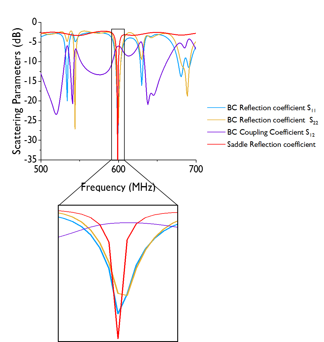
Figure 1: Scattering parameters
for loaded coils within a 200 MHz window around the resonance frequency.
Reflection and transmission coefficients (the latter is only relevant for the
quadrature BC coil) show the different resonance modes.
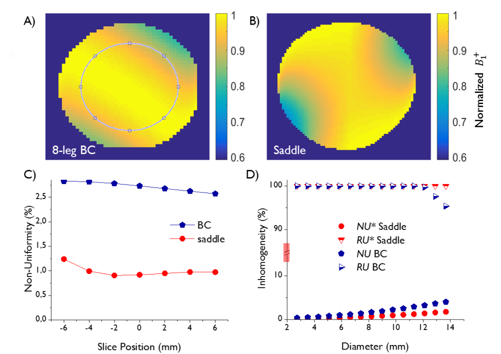
Figure 2: Simulated and normalized $$$B_1^+$$$ maps obtained from voxel-wise calculation $$$B_1^+=\theta/\gamma\tau\epsilon$$$, with 1H gyromagnetic ratio γ and
normalized pulse envelope correction factor ε = 0.413 for the applied Gaussian pulse. Axially centered $$$B_1^+$$$ maps generated by A) 8-leg BC and B) saddle coil. C) Dependence
of NU on the slice distance from the isocenter. Statistics were calculated within
an 11 mm diameter ROI (encircled in A)). D) NU and RU of the $$$B_1^+$$$ maps as a function of the ROI diameter on the
axially central slice (note the cut of the y-axis).
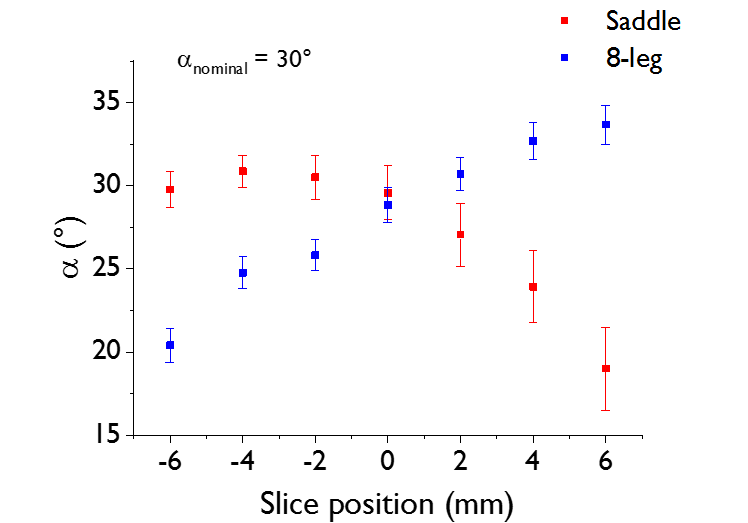
Figure 3: Mean effective
flip angle α over the excited slice as a function of slice position in z-direction (//$$$\vec{B_0}$$$)
for α calibrated to 30° in the center slice (position = 0 mm). Error
bars denote the standard deviation of the voxel-wise flip angles over a 11 mm
diameter central ROI (147 voxel). The same gradient echo sequence was used as for power
calibration measurements: TR = 10 s, TE = 2.6 ms, slice thickness = 2 mm, FOV = 25 x 25 mm2, matrix size =
32 x 32. The scale is chosen such that the origin is in the isocenter and
positive slice positions are in direction of the coil current source.
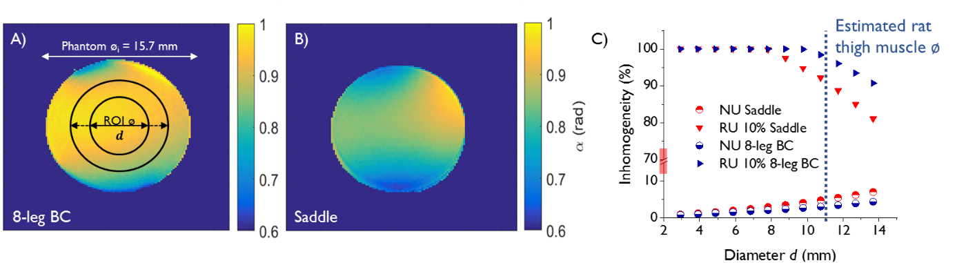
Figure 4: Transmit
field homogeneity analysis. Normalized $$$B_1^+$$$ maps of a 10 ml
0.9% saline phantom (inner diameter øi =
15.7 mm) generated by A) 8-leg
BC and B) saddle coil. $$$B_1^+$$$ maps were
created using the double angle method. Circles represent ROI positioning chosen
in C) for statistics. C) $$$B_1^+$$$ homogeneity was evaluated via RU and NU as a
function of ROI diameter. Acquisition was done with a gradient echo sequence
using TR / TE = 20000 / 4.83 ms, θ = 60° / 120°, matrix size = 128x128, FOV = 25x25
mm2.
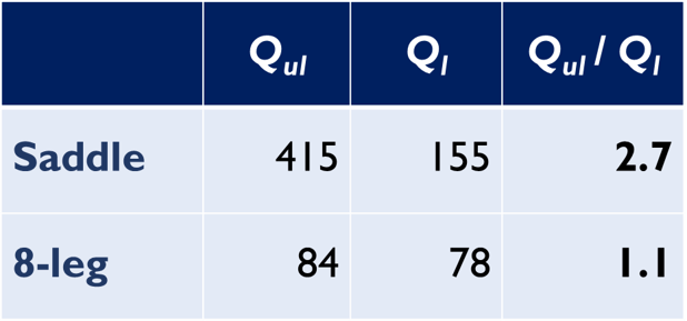
Table 1: Quality factors for
both coils in unloaded (Qul) and loaded (Ql) state with a 0.9% saline phantom (ø =
15.7 mm). Q-factors were measured on using the
network analyzer by dividing the center frequency by the -7 dB bandwidth.