4062
UHF MRI at 14 T: Initial transmit performance analysis of 8-channel local RF arrays using fractionated dipoles1Medical Physics in Radiology, German Cancer Research Center (DKFZ), Heidelberg, Germany, 2Electromagnetic Theory and Applied Mathematics, Faculty of Electrical Engineering and Information Technology, FH Aachen – University of Applied Sciences, Aachen, Germany, 3Erwin L. Hahn Institute for MRI, University Duisburg-Essen, Essen, Germany, 4Faculty of Physics and Astronomy and Faculty of Medicine, University of Heidelberg, Heidelberg, Germany
Synopsis
Numerical simulations were used to design and evaluate antenna arrays for body imaging at 14T. Previously presented fractionated dipole designs for 7T and 10.5T were adapted for 14T. Pulse optimization was performed in volumes with different sizes. In general, the RF shim performance decreases at higher RF frequency. The performance of 14T arrays in ROIs located in the body center is further limited by local SAR limits, as the SAR efficiency ($$$B_1^+$$$ normalized to $$$\sqrt{\operatorname{SAR}_{10g,max}}$$$) is lower in the body center.
Introduction
Since the introduction of MRI for medical imaging, there has been a continuous trend towards higher field strengths. Today, the strongest human-size MRI system operates at 10.5T.1 Furthermore, the first 11.7T systems were recently ramped up and 14T systems have been proposed.2,3For 10.5T, Ertürk et al. evaluated the RF shim capability of an 8-channel array consisting of fractionated dipoles placed close to the body and compared the results to 7T.1 Although the transmit field is less homogeneous at 10.5 T due to the shorter wavelength,4 it could be shown that with the use of 2 spokes, performance comparable to RF shimming at 7T can be achieved.1
In this study, an 8-channel array for body imaging at 14T (RF frequency of 600 MHz) has been designed and the transmit performance compared to the presented configurations at 7T (297 MHz) and 10.5T (447 MHz) using numerical simulations.
Methods
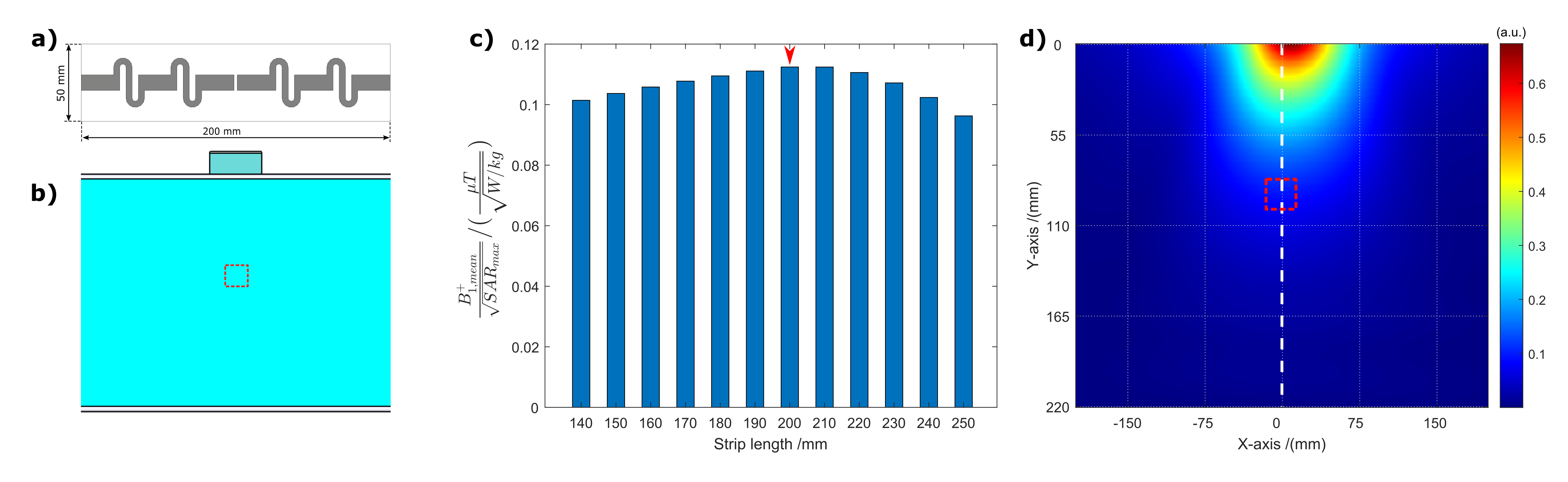
Fractionated dipole antennas with meander structures were simulated as single transmit elements and in an 8-channel local body array configuration. The dipole was placed on a 2 mm-thick PCB (FR-4). A 2 cm PMMA spacer was placed between PCB and subject.5First, the length of the 14T dipoles was optimized regarding maximum SAR efficiency ($$$B_1^+/\sqrt{\operatorname{SAR}_{10g,max}}$$$) in a (2 cm)³ volume 8-10 cm inside the tissue (similar to locations near the body center) using a single element placed on a homogeneous, tissue-simulating phantom ($$$\varepsilon_r^\prime$$$ = 39.98, $$$\sigma$$$ = 0.63 S/m at 14T), Figure 1. The antenna length was varied between 14 and 25 cm. For the other field strengths , antenna lengths of 30 cm (7T)5 and 21 cm (10.5T)1 were used and dielectric properties adjusted ($$$\varepsilon_r^\prime$$$ = 42.28, $$$\sigma$$$ = 0.56 S/m at 7T; $$$\varepsilon_r^\prime$$$ = 40.80, $$$\sigma$$$ = 0.59 S/m at 10.5T).
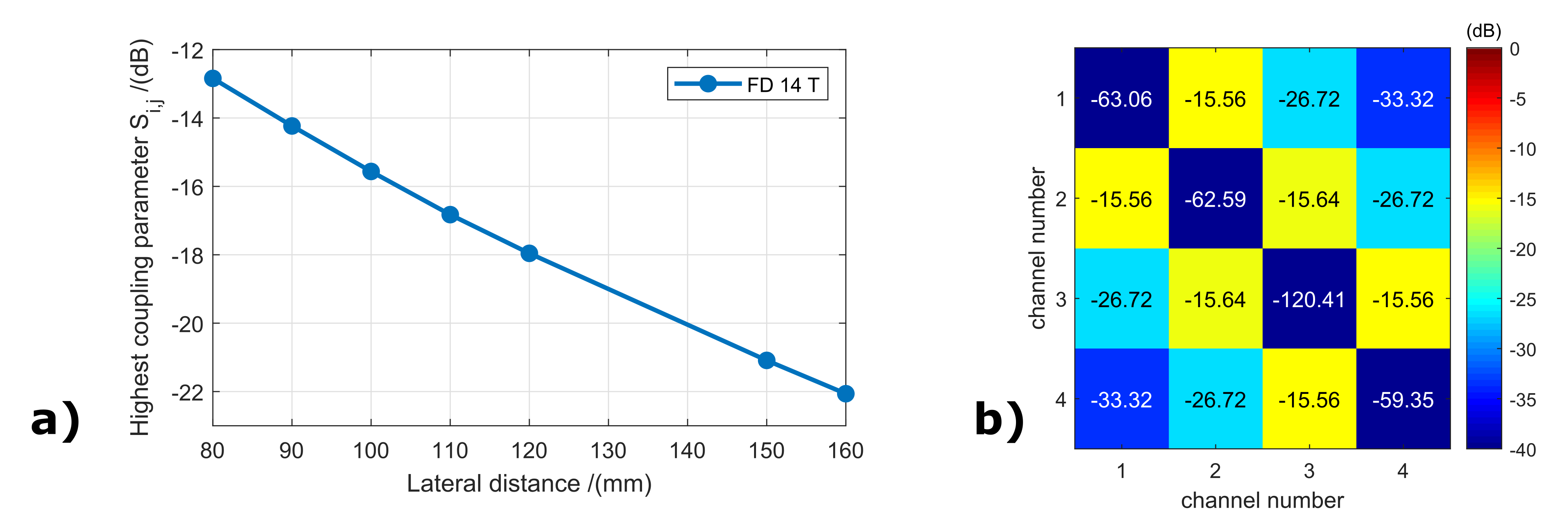
Next, the lateral spacing for 14T dipole arrays was optimized regarding inter-element coupling. Four elements were placed on a phantom with element separation between 8 and 16 cm. An inter-element coupling of -15 dB or better was considered to be sufficiently decoupled. No decoupling network was considered in this study. A lateral spacing of 9 cm as published for arrays at 7T5 and 10.5T1 was used for the other field strengths, Figure 3.
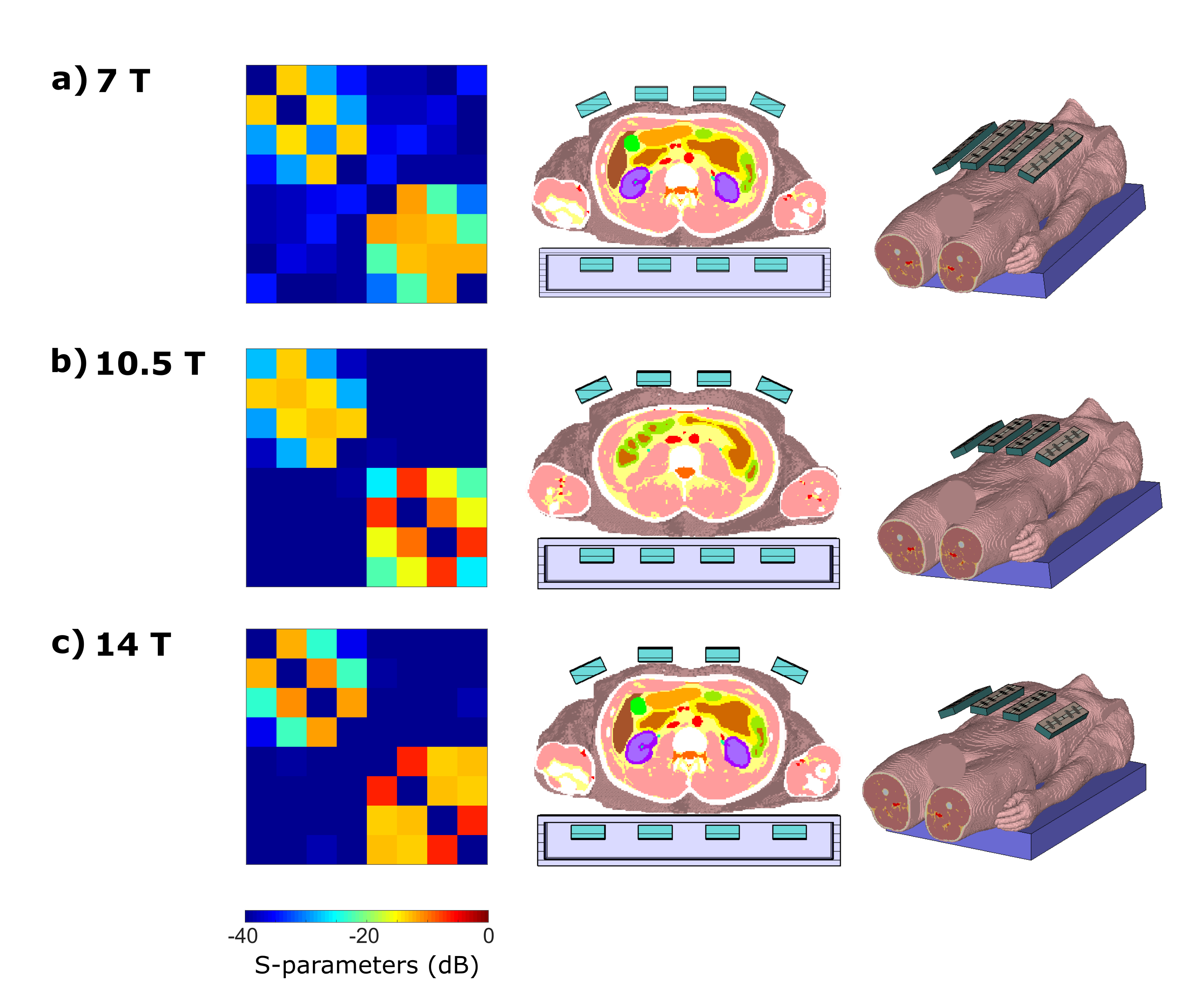
Finally, simulations with 8-channel arrays and a heterogeneous body model (male, 174 cm, 72.4 kg),6 placed head-first supine with the liver/kidney region in the array center, were performed to evaluate the transmit performance, Figure 4. RF simulations were performed in CST Studio Suite 2017 (CST AG, Darmstadt, Germany).
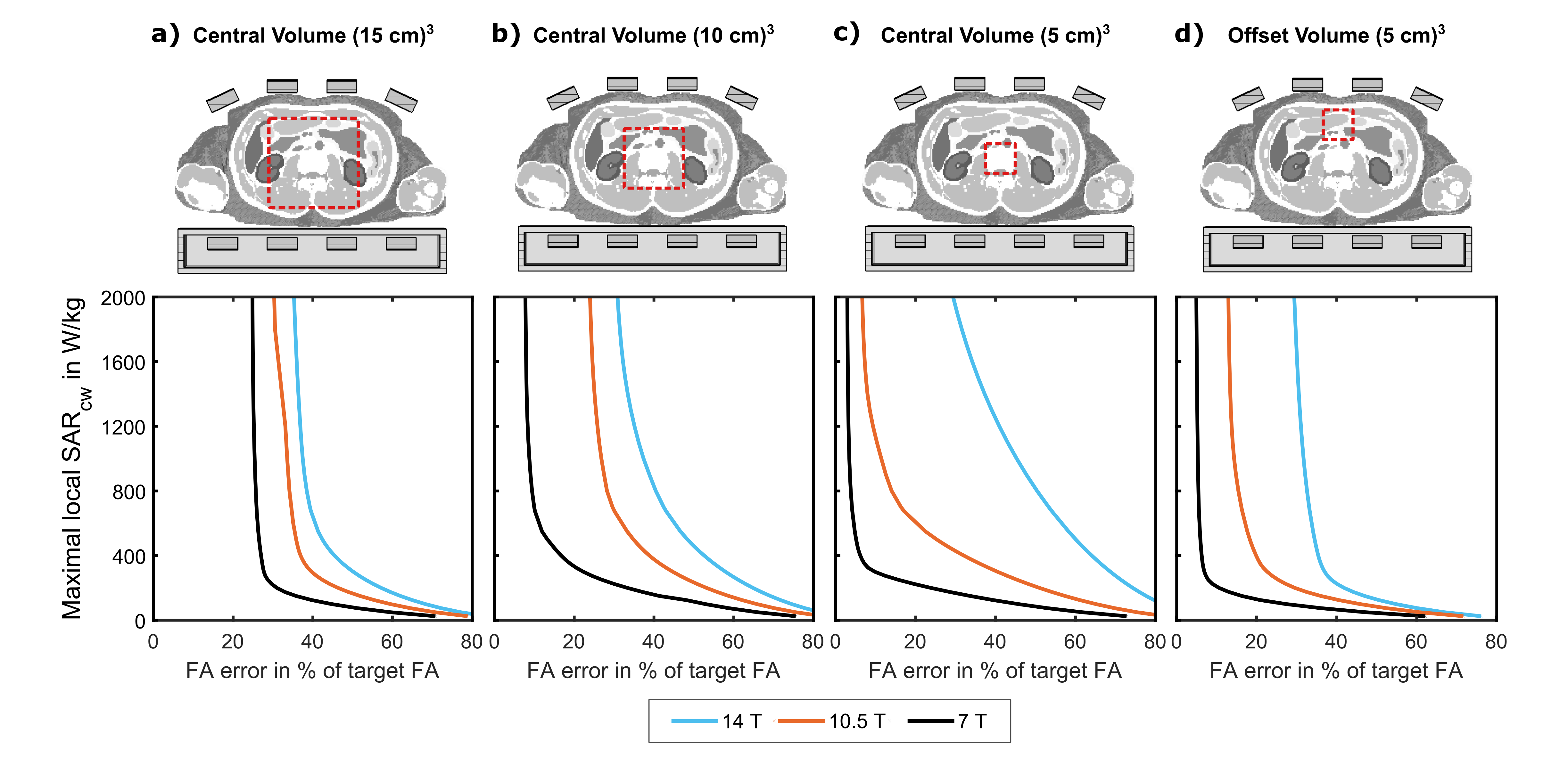
S-parameters as well as $$$B_1^+$$$ maps and electric fields for the individual channels were extracted. SAR matrices were computed and compressed using the virtual observation point algorithm.7 RF shimming for a target magnetization of 6.5 μT with peak power per channel of 1 kW and varying local SAR constraints9 was performed in a cubical volume with 5, 10, or 15 cm side length located centrally in the body. In addition, a (5 cm)3 volume located beneath the anterior body surface was evaluated.
Results
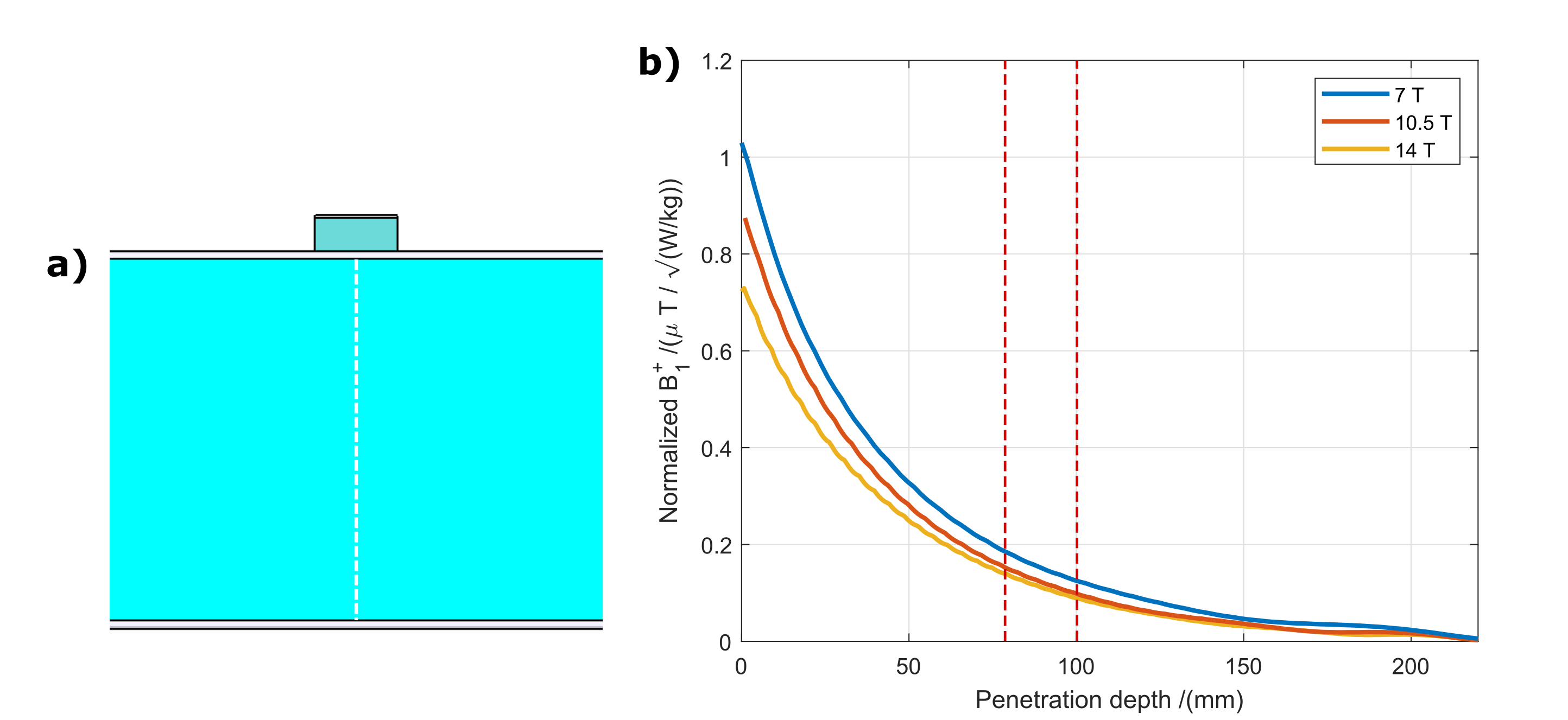
The evaluation of the SAR efficiency for the 14T dipole shows an optimal length of 20 cm, Figure 1. The SAR efficiency as a function of tissue depth in the phantom is plotted for all three field strengths in Figure 2. In the defined ROI, the 7T array shows the highest efficiency, while a lower, almost equal efficiency was found for 10.5T and 14T. The smallest lateral spacing for the dipole elements at 14T, allowing coupling below -15 dB, was found for 10 cm, Figure 3. In the 8-channel array configurations, all array elements were matched to -40 (14T), -13 (10.5T), and -12 (7T) dB or better. The simulations with a body model show increased inter-element coupling with a maximum of -6.3 dB at 14T, Figure 4. However, the implementation of decoupling networks in a further study could reduce coupling, although they were not considered here. Results for the pulse optimization are shown in Figure 5 in the form of L-curves without duty cycle (continuous wave (cw) signal). In all considered ROIs, the shim performance generally decreases for higher RF frequencies. The 7T and 10.5T arrays show a higher performance for smaller ROIs. In contrast, the 14T array shows in smaller ROIs a slight improvement only for high SAR (SARCW>1800 W/kg). For lower SAR, the shim performance is decreased. As the 14T antennas have a lower SAR efficiency at deeper tissue depths (Figure 2), a higher transmit power and thus a higher SAR is necessary to excite these regions. Thus, a (5 cm)³ ROI located beneath the surface was evaluated, showing an improved shim performance at 14T compared to the center ROI.Conclusion
The dipole antenna design, presented for 7T5 and 10.5T1, was adjusted for 14T. Antenna length and lateral element spacings for transmit arrays were therefore optimized in this study. Simulations of 8-channel body arrays show general applicability at 14T. However, the imaging performance in the center of the body at 14T is more strongly limited by the local SAR limits, which remain unchanged compared to lower field strengths.4,9Acknowledgements
References
1Ertürk et al. Toward Imaging the Body at 10.5 Tesla. Magn Reson Med. 2017, 77:434–443
2Institute of research into the fundamental laws of the Universe. Website: http://irfu.cea.fr/en/Phocea/Vie_des_labos/Fait_marquant/index.php?id_news=4040. Last accessed: 15.10.2019
3German Council of Science and Humanities (Wissenschaftsrat). Bericht zur wissenschaftsgeleiteten Bewertung umfangreicher Forschungsinfrastrukturvorhaben für die Nationale Roadmap (Drs. 6410‐17). Cologne, Germany, 2017. https://www.wissenschaftsrat.de/download/archiv/6410-17.pdf?__blob=publicationFile&v=2. Last accessed: 15.10.2019
4Fiedler TM, Ladd ME and Bitz AK. SAR Simulations & Safety. NeuroImage. 2018 Mar;168:33-58.
5Raaijmakers et al. The fractionated dipole antenna: A new antenna for body imaging at 7 Tesla. Magn Reson Med. 2016, Mar;75(3):1366-74.
6Christ et al. The Virtual Family--development of surface-based anatomical models of two adults and two children for dosimetric simulations. Phys Med Biol. 2010, an 21;55(2):N23-38.
7Eichfelder G and Gebhardt M. Local Specific Absorption Rate Control for Parallel Transmission by Virtual Observation Points. Magn Reson Med. 2011, 66:1468–1476.
8Guérin et al. Design of parallel transmission pulses for simultaneous multi-slice with explicit control for peak power and local specific absorption rate. Magn Reson Med. 2015, 73(5):1946-1953.
9IEC 60601-2-33, Edition 3.2. 2015 Medical electrical equipment – Part 2-33: Particular requirements for the basic safety and essential performance of magnetic resonance equipment for medical diagnosis.
Figures