4060
An automatic tuning free pin diode shunt switch with artificial non-uniform transmission line λ/4 sections for receive only surface array coils.
Miheer Pradeep Mayekar1, Rohit Apurva1, Bhaskara Naik1, and Rajesh Harsh1
1Technology Innovation Department, Society for Applied Microwave Electronics Engineering and Research, Mumbai, India
1Technology Innovation Department, Society for Applied Microwave Electronics Engineering and Research, Mumbai, India
Synopsis
The excessive high-power during transmission saturates or in worst case damages the preamplifier. In shunt switch an artificial (lumped component) uniform λ/4 section is inserted between two shunt diodes to increase its isolation. To restore the preamplifier-decoupling performance degraded by λ/4 section, it is required to add lossy tuning components e.g. varactor diodes to change the λ/4 section’s phase. We are proposing a pin-diode shunt RF switch with two lumped component non-uniform λ/4 sections which will maintain the preamplifier decoupling performance during reception sans complex tuning components and provides additional isolation of around 10-db as compared to uniform λ/4 sections.
Synopsis
The excessive high-power during transmission saturates or in worst case damages the preamplifier. In shunt switch an artificial (lumped component) uniform λ/4 section is inserted between two shunt diodes to increase its isolation. To restore the preamplifier-decoupling performance degraded by λ/4 section, it is required to add lossy tuning components e.g. varactor diodes to change the λ/4 section’s phase. We are proposing a pin-diode shunt RF switch with two lumped component non-uniform λ/4 sections which will maintain the preamplifier decoupling performance during reception sans complex tuning components and provides additional isolation of around 10-db as compared to uniform λ/4 sections.Introduction
During transmission period in MRI high power RF signal induces large voltage level in receive only surface coils. According to Faraday's law of electromagnetic induction (equation 1), the induced voltage in a single turn wire loop is proportional to its area ‘A’ and incident magnetic field ‘B1’.$$V_{coil} = -A_{coil}\frac{dB_{1}(t)}{dt}\cdot\cdot\cdot\cdot\cdot\cdot\cdot\cdot\cdot\cdot(1)$$
B1 field required for a specific flip angle ‘α’ is given by equation 2,
$$\alpha=\gamma\int_{0}^{t_{p}} B_{1} (t)dt\cdot\cdot\cdot\cdot\cdot\cdot\cdot\cdot\cdot\cdot(2)$$
For rectangular pulse of duration and constant amplitude B1, flip angle in degrees and gyromagnetic-ratio γ, is given by equation1,
$$B_1=α/(360γt_p ) [Tesla]\cdot\cdot\cdot\cdot\cdot\cdot\cdot\cdot\cdot\cdot (3)$$
Typically, the value of B1 is under 50 µT2. Power generated by receive only coil during transmission typically ranges from 26 to 42 dbm3. At such high power, surface coil’s diode decoupling performance deteriorates which passes significant amount of high power to preamplifier, which follows the coil as shown in figure 1. Additionally, according to failure mode effect analysis (FMEA) during first fault condition when diode trap fails entire generated power by coil appears at the preamplifier input4. This excessive high-power during transmission sometimes saturates or in worst case damages the preamplifier. In order to protect preamplifier from this excessive high power we need RF switch before it as shown in figure 15. Pin diode switches are widely used because of their high-power handling and low nonlinear distortion as compared to FET switches. Shunt pin diode-based RF switch is preferred over series because of its low insertion loss but it also provides low isolation as compared to series switch. According to A. M. Street6 placing multiple diodes in parallel is not an attractive solution to increase the isolation. Instead, artificial uniform transmission line λ/4 sections are inserted between multiple shunt diodes to increase the switch’s isolation. Typically, Commercial Off the Shelf (COTS) surface coil preamplifiers7 can handle up to 30 dbm of input power and have output P1 db of 9 dbm. Hence in order to protect preamplifier we need around 60 to 70 db isolation from switch. A shunt switch with two diodes separated by a uniform λ/4 section is a logical choice to achieve above mentioned figure with acceptable insertion loss. As shown in figure 1, integer multiple of -180⁰ phase needs to be maintained between coil and preamplifier in order to achieve preamplifier decoupling. If this -180⁰ phase is achieved by using cable trap and coaxial cable by taking manoeuvrability/position of coil in to consideration then addition of above-mentioned switch will distort the -180⁰ phase setting and furthermore it degrades the preamplifier decoupling during reception. To maintain the -180⁰ phase, we have to modify the phase of λ/4 section during reception by using tuning components e.g. varactor diodes, pin diode-based capacitor bank etc.8,9. These tuning components are lossy and require complex tuning mechanism9,10. To solve this issue, we are proposing to add one more uniform λ/4 section after the switch to maintain the -180⁰ phase. Through analysis and measurement, we have showed that addition of non-uniform λ/4 sections instead of uniform improves the isolation of switch with negligible increase in insertion loss.
Methods
S-parameter of the switch design shown in figure 2 is given by equation 4,$$S_{21} = \frac{2√(R_{01}R_{02}) }{AZ_{02}+B+CZ_{01} Z_{o2}+DZ_{o1}}\cdot\cdot\cdot\cdot\cdot\cdot\cdot\cdot\cdot\cdot(4)$$
Where, A, B, C and D are ABCD parameters and Zo1=Zo2 are real impedances. For switch with uniform λ/4 sections, Zo1=Zo1'=Zo2'=Zo2 and with non-uniform λ/4 sections, Zo1<Zo1'=Zo2'>Zo2, Zo1=Zo2.
From equation 4 it is evident that isolation can be improved by increasing the characteristic impedance of uniform λ/4 sections. However, this is not acceptable as COTS surface coil preamplifiers are designed for 50 Ω source impedance to achieve minimum noise figure and this fact restricts characteristic impedance of uniform λ/4 sections to 50 Ω. By using non uniform λ/4 sections improvement in isolation can be achieved along with maintaining source impedance of preamplifier.
Results
For concept’s demonstration we have considered Zo1=Zo2=50 Ω, Zo1'=Zo2'=200 Ω, used Microsemi’s UM9995 pin diodes and WanTcom’s-WMA1T5AE preamplifier. We have demonstrated preamplifier decoupling with 5” diameter copper wire coil tuned at 63.87 MHz and matched to 50 Ω. Figure 3 and 4 illustrates the simulated and measured results of switch respectively. Figure 5 illustrates the complete setup of measurement.Discussion and Conclusion
The proposed switch design is a simple alternative to more complex and lossy-configurable design which uses tuning components. We are expecting that the proposed simplified design will help to reduce the cost of overall system which is in line with our mission of low-cost MRI development.Acknowledgements
Authors are thankful to Mr. Tapas Bhuiya, Mr. Niraj Yadav and Mr. Vishal Boricha for their support.References
- http://mriquestions.com/what-is-flip-angle.html
- Taracila V, Chan P, Robb F. Minimal acceptable blocking impedance for RF receive coils. Proc Int Soc Magn Reson Med.2010;18:3928.
- Ganti, A, Ortiz, T, Wynn, TA, Lin, J, Duensing, R. Effect of PIN diode nonlinearity on decoupler circuits in magnetic resonance imaging surface coils. Concepts Magn Reson Part B. 2018; 48B:e21398.
- B. L. Beck, G. R. Duensing, Design of Decoupling Circuits for Patient Safety, Proceedings of the International Society for Magnetic Resonance in Medicine, 1997.
- Arne Reykowski, Rodney Housen, Fet Switch As Detune Circuit For MR RF Coils, US Patent, US 9,720,060 B2.
- A. M. Street, "RF switch design," IEE Training Course How to Design RF Circuits, London, UK, 2000, pp. 4/1-4/7.
- https://www.wantcominc.com/DataSheets/WMA/WMA1T5AE.pdf
- Matteo Pavan, Roger Lüchinger, and Klaas Paul Pruessmann, Noise Contributions In Receive Coil Arrays, Proc. Intl. Soc. Mag. Reson. Med. 20 (2012).
- Sung-Min Sohn, RF and Electronic Design Perspective on Ultra-High Field MRI systems, Ph.D. thesis, University Of Minnesota, February 2013.
- http://www.ricksturdivant.com/2016/07/09/varactophaseshifter/
Figures
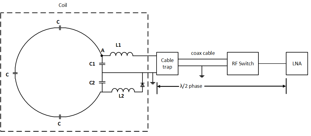
Fig. 1 Receiver chain for single receive only surface coil
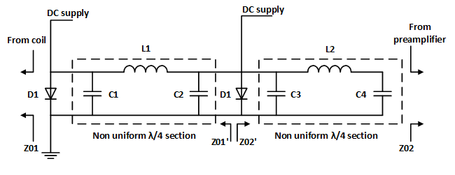
Fig. 2 Shunt switch's circuit diagram
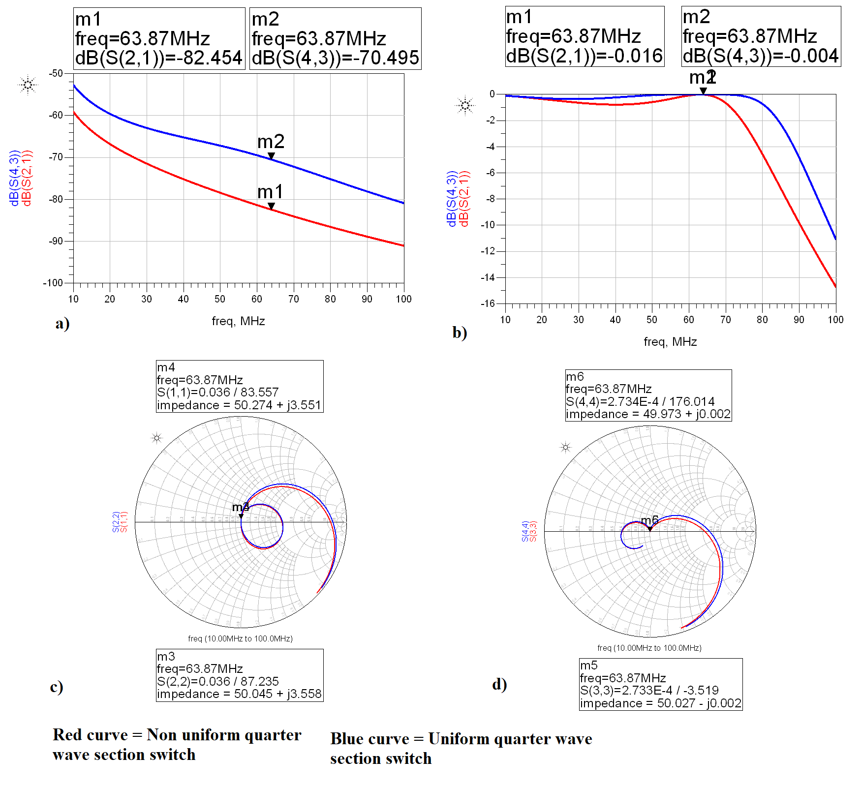
Fig. 3 a) Isolation. b) Insertion. c) and d) Matching at two ports when switch is in Insertion state.
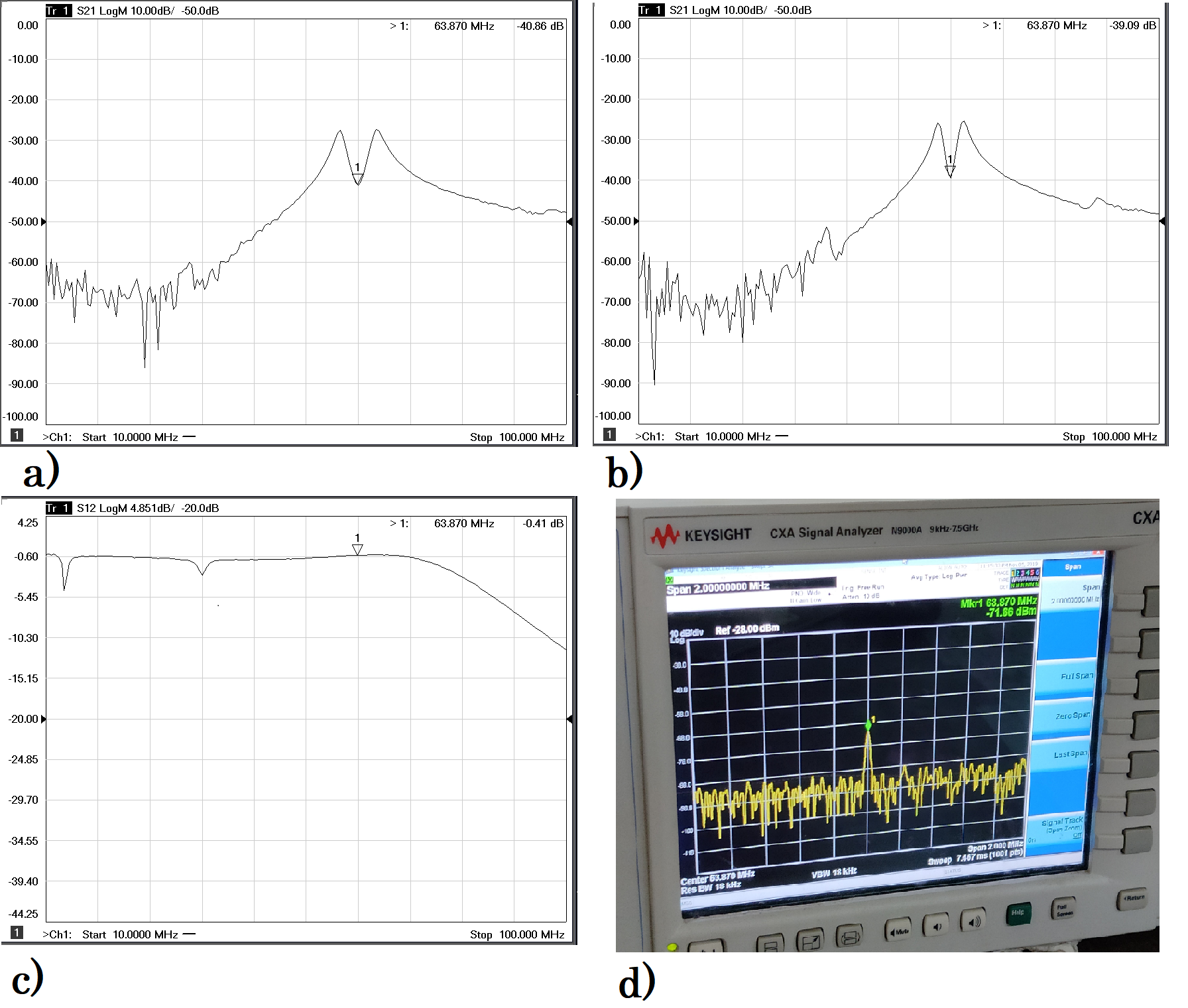
Fig. 4 a) Measured preamplifier decoupling (~15 db) before adding non-uniform λ/4 section switch. b) Measured preamplifier decoupling (~ 13 db) after adding non-uniform λ/4 section switch. c) Insertion loss (0.4 dB) of non-uniform λ/4 section switch. d) Isolation measured on spectrum analyser (~85 dB) with input power of 15 dBm.
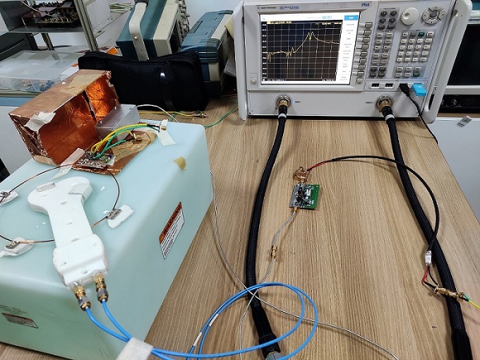
Fig. 5 Complete setup for preamplifier decoupling measurement.