4059
A flexible five-channel shielded-coaxial-cable transceive neck coil for high resolution carotid imaging at 7T1Radiology Department, Leiden University Medical Center, Leiden, Netherlands
Synopsis
Imaging the carotid arteries at 7T requires a multichannel array which allows B1-shimming and conforms to different neck sizes. The major challenge is to minimise coupling between closely-spaced coils and to make the coupling relatively insensitive to loading conditions. We have designed a five channel transceive array composed of shielded-coaxial-cable coils placed on the anterior part of the neck and conforming to the anatomy. Coil flexibility has been demonstrated by imaging subjects with different neck circumferences. In vivo black-blood images were acquired with very high in-plane spatial resolution (0.25 x 0.25 mm2) with clear depiction of the vessel walls.
Introduction
Very high resolution imaging of the carotid arteries is potentially an area in which high field MRI could play a major role. Several studies have acquired data on single or both carotids using either single surface coils1, a transmit array of surface coils2,3, or a concept using a leaky wave antenna and the transmit small surface loops for receive4,5. The biggest limitation of carotid imaging arrays so far is the lack of adaptability to the neck geometry of the people with various BMIs (Body Mass Index). The high inter-element decoupling in such arrays is desirable, and should not change substantially when the individual coil elements are geometrically stretched or compressed due to different neck sizes. To address these issues we have designed a flexible neck array with shielded-coaxial-cable (SCC) coils6.Methods
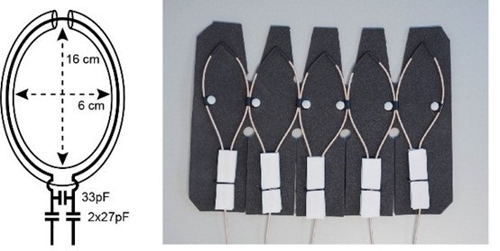
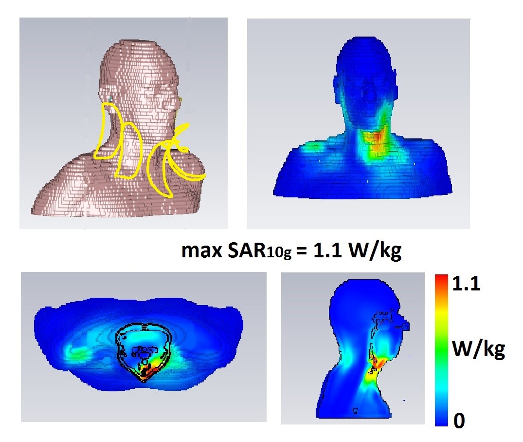
Each elongated shielded-coaxial-cable (SCC) loop coil (Figure 1a), with minor axis 60 mm and major axis 160 mm, were constructed from thin 50 Ohm coaxial cable (Huber+Suhner K 02252 D-06, diameter 3.0 mm) with a balanced capacitive pi-matching network. The transceive array was constructed of five identical SCC loop coils spaced 5 mm apart (Figure 1). The elements were attached to a flexible foam former, thickness 10 mm. The array elements were tuned to a volunteer with neck circumference of 370 mm.Electromagnetic simulations were performed in CST Microwave Studio 2019 (CST Studio Suite, Computer Simulation Technology, Darmstadt, Germany). To evaluate SAR10g, in vivo simulations using the voxel model Gustav was used (with a neck circumference ~375 mm). The calculated SAR10g was normalized to 1W of accepted power. Different excitation phases, corresponding to B1+ shimming, were investigated and the one corresponding to maximum SAR10g is shown in Figure 2.
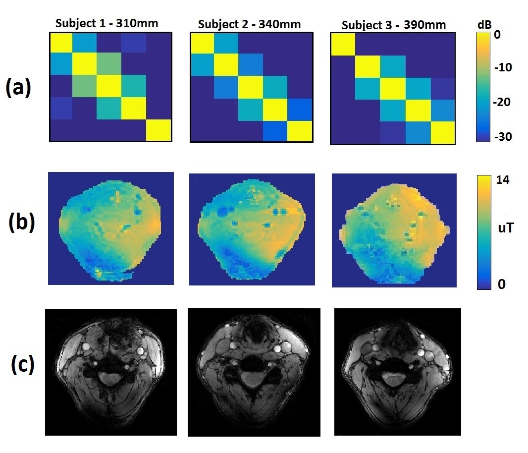
The dual refocusing echo acquisition mode (DREAM)7 sequence was used to acquire B1+ maps with the following parameters: FOV = 200 × 160 × 25 mm3, voxel size = 5 × 5 × 5 mm3, flip angle = 10°, STEAM angle = 50°, TE/TR = 1.97/15 ms, 1 signal average.
Based on the in vivo B1+ maps, phase‐based RF shimming was performed using five individual transmit channels in order to optimize the transmit homogeneity within both carotids simultaneously.
Anatomical localizer imaging of the carotids was performed with a gradient echo sequence using the following parameters: FOV = 140 × 140 mm2, voxel size = 0.6 × 0.6 × 4.0 mm3, flip angle = 25°, TR/TE= 300 / 6.4 ms, number of averages = 4.
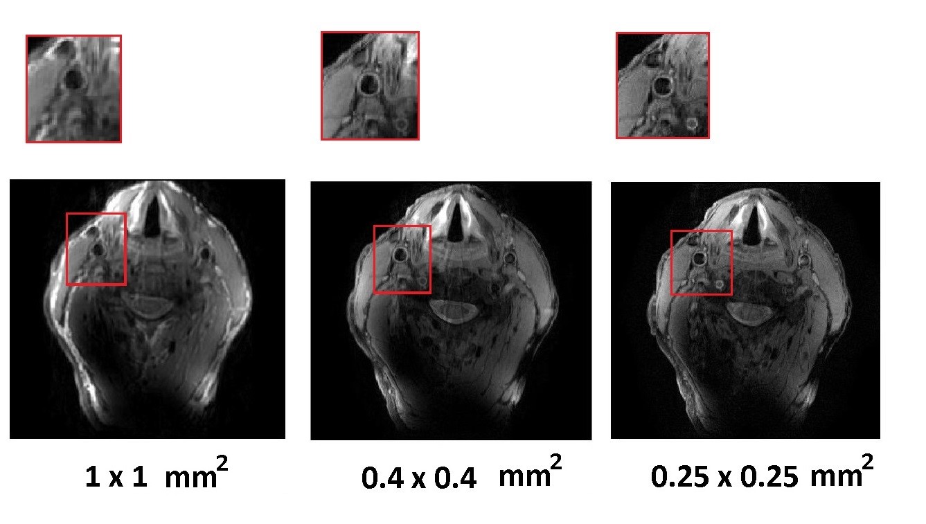
Black blood imaging at different spatial resolutions was performed with a multi-slice (MS) turbo spin echo (TSE) sequence using the following parameters: FOV = 140 × 140 mm2, echo train length = 12, number of averages = 1:
(i) voxel size = 1 × 1 × 2.0 mm3 - TE/TR = 7.9 / 4958 ms
(ii) voxel size = 0.4 × 0.4 × 2.0 mm3 - TE/TR = 9.8 / 5240 ms
(iii) voxel size = 0.25 × 0.25 × 2.0 mm3 - TE/TR = 11 / 2622 ms
Results
Figure 2 shows a maximum simulated SAR10g of 1.1 W/kg on the voxel model, which is well below the allowed value: this corresponded to equal excitation phases for each element of the array. Figure 3 (a) shows measured noise correlation matrices on three subjects (1 male, 2 female) with neck circumferences of 310 mm, 340 mm and 390 mm. The coupling coefficients were -12.5 dB and below for all subjects and all coils. Figure 3 (b) shows the measured B1+ maps. The B1+ in a carotid regions were between 12.6 and 16.8 µT (for both right and left carotid). We should note that the B1+ in the carotid arteries themselves cannot be measured due to flow. Figure 3 (c) shows gradient echo images of the carotids, with the carotids appearing bright due to in-flow effects. Figure 4 shows ‘’black blood’’ TSE images of the carotid artery at different in-plane spatial resolutions (1 x 1 mm2, 0.4 x 0.4 mm2 and 0.25 x 0.25 mm2), with zoomed-in magnifications to show the excellent depiction of the vessel wall.Discussion
Previous work has shown that an SCC coil has high intrinsic decoupling from surrounding elements, and that the bending and elongation of the coil does not influence its performance as much as the conventional loop coil6 making it very suitable for a flexible array. The simulated max SAR10g of 1.1 W/kg was less than the 1.27 W/kg2 and 1.99 W/kg5 reported for other coil arrangements. The coil flexibility was demonstrated by imaging of three subjects with very different neck circumferences, with the measured noise correlation coefficients being stable with respect to the neck dimensions.Conclusions
In this paper, we designed a highly flexible 5-element array for imaging of the carotid arteries at 7 T. The fabricated array can be positioned tightly onto the anterior neck region and can be bent to follow the anatomy of the region. Using this array we have achieved very high resolution, 0.25 x 0.25 mm2 in-plane black blood carotid imaging in a single acquisition.Acknowledgements
This work was funded by ERC NOMA-MRI 670629.References
1. Kroener ES, van Schinkel LD, Versluis MJ, Brouwer NJ, van den Boogaard PJ, van der Wall EE, de Roos A, Webb AG, Siebelink HM, Lamb HJ. Ultrahigh-field 7-T magnetic resonance carotid vessel wall imaging: initial experience in comparison with 3-T field strength. Invest Radiol. 2012;47(12):697-704.
2. Kraff O, Bitz AK, Breyer T, et al. A transmit/receive radiofrequency array for imaging the carotid arteries at 7 tesla: coil design and first in vivo results. Invest Radiol. 2011;46:246-254.
3. Papoutsis K, Li L, Near J, Payne S, Jezzard P. A purpose-built neck coil for black-blood DANTE-prepared carotid artery imaging at 7T. Magn Reson Imaging. 2017;40:53-61.
4. Coning W, De Rote AAJ, Bluemink JJ, van der Elden TA, Listen PR, Clomp DWJ, et al. MRI of the carotid artery at 7 tesla: quantitative comparison with 3 tesla. J Man Reason Imaging. 2015;41:773-780.
5. Coning W, Bluemink JJ, Agenize EAJ, Rainmakers AJ, Andreessen A, van den Berg CAT, et al. High-resolution MRI of the carotid arteries using a leaky waveguide transmitter and a high-density receive array at 7 T. Man Reason Med. 2013;69(4):1186-1193.
6. Ruytenberg T, Webb A, Zivkovic I. Shielded‐coaxial‐cable coils as receive and transceive array elements for 7T human MRI. Magn Reson Med 2019; DOI: 10.1002/mrm.27964
7. Nehrke K, Bornert P. DREAM ‐ a novel approach for robust, ultrafast, multislice B‐1 mapping. Magn Reson Med. 2012;68:1517–1526.
Figures