4058
Feasibility study of volume RF coils constructed using coupled H-shaped dipole antennas for MR imaging at ultrahigh fields
Shasha Yue1, Zhe Wang1, Cheng Fang1, Nan Li2, Yan Hou1, Kun Zhang1, Rong Xue3,4,5, Ye Li2,6, and Xiaoliang Zhang7
1Institute of Biophysics, Chinese Academy of Sciences, Beijing, China, 2Lauterbur Imaging Research Center, Shenzhen Institutes of Advanced Technology, Chinese Academy of Sciences, Shenzhen, China, 3State Key Laboratory of Brain and Cognitive Science, Beijing MRI Center for Brain Research, Institute of Biophysics, Chinese Academy of Sciences, Beijing, China, 4University of Chinese Academy of Sciences, Beijing, China, 5Beijing Institute for Brain Disorders, Beijing, China, 6Shenzhen Key Laboratory for MRI, Shenzhen, China, 7Department of Biomedical Engineering, State University of New York, Buffalo, NY, United States, Buffalo, NY, United States
1Institute of Biophysics, Chinese Academy of Sciences, Beijing, China, 2Lauterbur Imaging Research Center, Shenzhen Institutes of Advanced Technology, Chinese Academy of Sciences, Shenzhen, China, 3State Key Laboratory of Brain and Cognitive Science, Beijing MRI Center for Brain Research, Institute of Biophysics, Chinese Academy of Sciences, Beijing, China, 4University of Chinese Academy of Sciences, Beijing, China, 5Beijing Institute for Brain Disorders, Beijing, China, 6Shenzhen Key Laboratory for MRI, Shenzhen, China, 7Department of Biomedical Engineering, State University of New York, Buffalo, NY, United States, Buffalo, NY, United States
Synopsis
The feasibility of constructing the non-array volume RF coil using the coupled dipole antennas has been explored. The electromagnetic coupling among the dipoles is relatively weak and not readily to form a volume coil unless massive and dense dipoles are employed. An H-shaped dipole is proposed as the basic resonant elements to construct the ultrahigh field volume RF coil. The simulation and imaging experiment results show that the proposed H-shaped dipoles can achieve sufficient electromagnetic coupling with a much-reduced number of dipoles and form a volume coil with a practical coil length and uniform B1 fields in an efficient way.
Introduction
Dipole antenna has demonstrated a unique capability of achieving high resonant frequency and utility in high field MR imaging [1,2]. Previous work demonstrated that it is feasible to construct a non-array volume RF coil using coupled dipole antennas [3] where the dipole antennas equidistantly placed in parallel to form a cylinder-shaped volume coil with multi-model resonance behavior through electromagnetic coupling among the dipoles, although the coupling is weak, and generate uniform B1 field distribution for MR imaging. In practice, the arm length of a half-wave dipole is long at the corresponding frequency, which is not conducive to imaging application, even at the ultrahigh field of 9.4T[4]. Additionally, the electromagnetic coupling among the dipoles is relatively weak and not readily to form a volume coil unless massive and dense dipoles are employed. In this work, an H-shaped dipole is proposed as the basic resonant elements to construct the ultrahigh field volume RF coil. The results show that the proposed H-shaped dipoles can achieve sufficient electromagnetic coupling with a much-reduced number of dipoles and form a volume coil with a practical coil length and uniform B1 fields in the imaging region. This design makes dipole antenna non-array volume coil with very little capacitor for MR imaging at high and ultrahigh fields.Methods
The H-shaped dipole likes that the end part of the regular dipole arm spilt into two parts, as showed in figure 1(a). The angle of this two-split part can be adjusted as required. Several H-dipoles are equally placed in parallel to form the volume coil and their arms are staggered a bit to avoid connecting together, as showed in figure 1(b) and figure 1(c). The behavior of the constructed volume RF coil is evaluated by the electromagnetic simulations, which were performed with FDTD method in CST studio. Three planes of B1 fields of the volume coil for 400MHz/600MHz and 4/8 dipole antennas were numerically mapped. The angle of the two-spilt part is 90 degrees for 4-element volume coil and 135 degrees for 8-element volume coil.The prototype of the 4-element 400MHz volume coil with diameter of 120mm is built with copper wires and only one trimmer, as showed in figure1(d). The S11 match of -65dB was achieved by placing a trimmer in parallel with the drive port, figure1(e). Phantom experiment was implemented on the 9.4T MRI system in the Institute of Biophysics, Chinese Academy of Sciences. Phantom images were acquired with a FLASH sequence (TR/TE=300ms/9ms,, FOV= 100 mm, Matrix size=256 x 256)。
Results
The electric and magnetic field of one single H-shaped dipole is showed in Figure 2, of which the angle of the two spilt arm parts is 180 degree. The electric filed near the four arm ends of the H-shaped dipole antenna is all strong. The antennas get sufficient induction from others through the overlap of the end split parts. For 400MHz and 600MHz of 4-element coil, the B1 field distribution of the one port volume coil in the center horizontal xy plane and the center vertical xz/yz plane is showed in Figure 3 and figure 4, demonstrating a fairly homogeneous B1 field distribution. Although the volume coil is composed with only 4 H-shaped dipole antennas and the size of volume is larger, one dipole is excited, the rest of dipoles are also excited together. This behavior is also demonstrated in the simulation results of a 400MHz 8-element coil, of which the B1 map is showed in Figure 5. The axial image of the water phantom at 9.4T is showed in Figure1(f), and the excited B1 field is relatively uniform.Discussion/Conclusion
The non-array volume coil constructed with few H-shaped dipoles can generate sufficient electromagnetic coupling among the dipoles and the homogeneous magnetic field. The electromagnetic coupling is enhanced due to the capacitance caused by the overlap of the bent tips of the adjacent dipoles. The capacitance could hold the electric energy and help to diminish the electric field in the imaging area and thus SAR in the imaging subject, making MRI safer. The proposed H-shaped dipoles also help the volume coil to achieve a practical coil length and increase the efficiency of signal excitation and reception. The proposed H-shaped dipole volume coil potentially suggests a new way to design high frequency large-sized non-array volume coils for ultrahigh field MR imaging applications. In the future, more experiments with lager size, more dipole elements and more dedicated fabrication will be implement on the continuously optimized MRI system.Acknowledgements
References
[1] Raaijmakers A J E, Ipek O, Klomp D W J, et al. Design of a radiative surface coil array element at 7 T: the single‐side adapted dipole antenna[J]. Magnetic resonance in medicine, 2011, 66(5): 1488-1497. [2] Yan X, Zhang X, Wei L, et al. Design and test of magnetic wall decoupling for dipole transmit/receive array for MR imaging at the ultrahigh field of 7T[J]. Applied magnetic resonance, 2015, 46(1): 59-66. [3] Shasha Y, Chao L, Nan L, et al. Feasibility exploration of constructing volume RF coil with coupled dipole antennas at 9.4T[C]//Proc. 26th Annu. Meeting ISMRM. 2018. [4] Raaijmakers A J E, Italiaander M, Voogt I J, et al. The fractionated dipole antenna: A new antenna for body imaging at 7 T esla[J]. Magnetic resonance in medicine, 2016, 75(3): 1366-1374.Figures
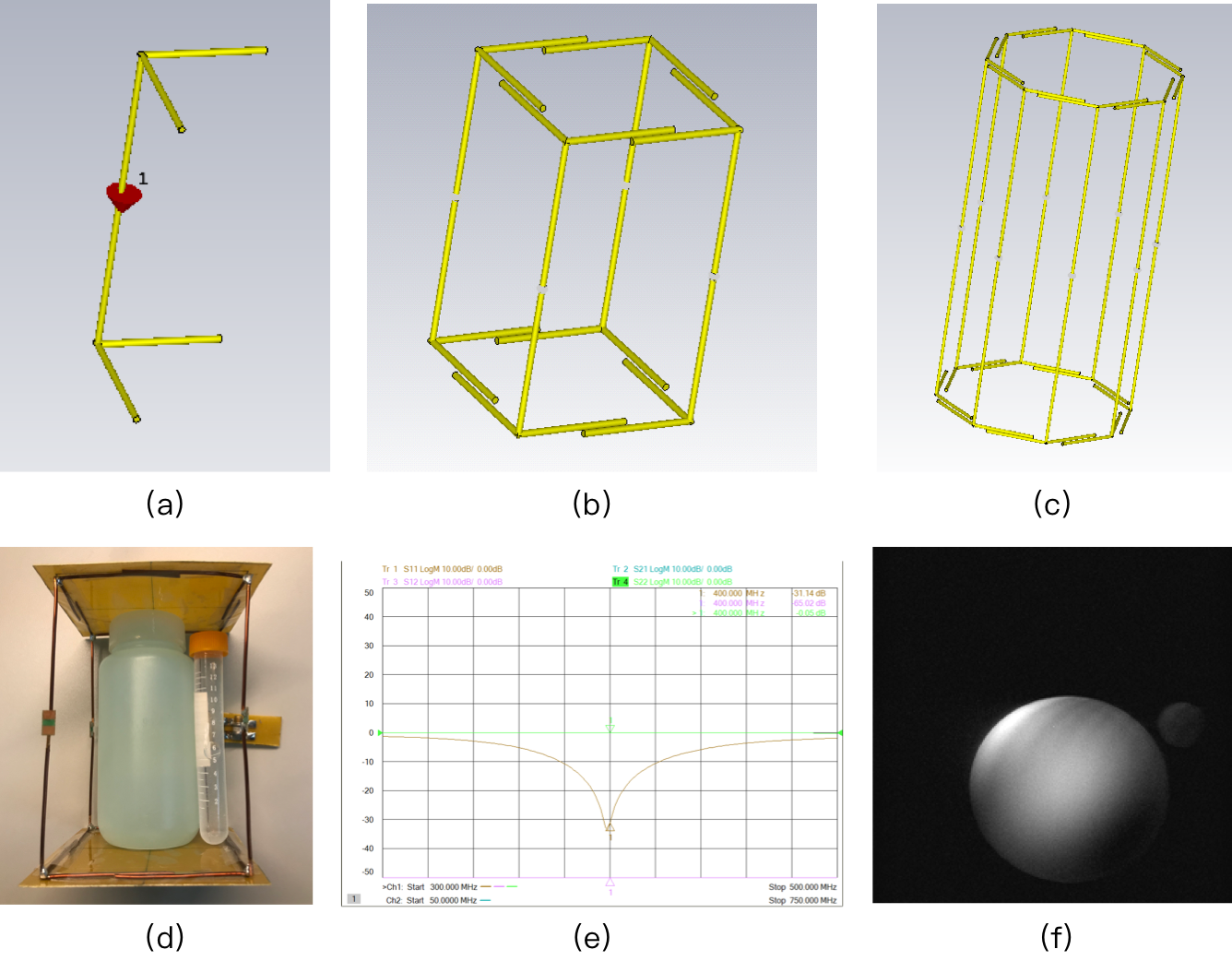
Figure1.
(a) schematic of the H-shaped dipole antenna; (b) schematic
of the volume RF coil composed of 4 H-shaped dipole antenna; (c) schematic of
the volume RF coil composed of 8 H-shaped dipole antenna; (d) the prototype of
the 4-element
400MHz volume coil and the phantom; (e)
S11 plot of the coil; (f) The axial image of the water phantom acquired at 9.4T
(the non-uniform image pattern may indicate the dielectric effect at the 400
MHz in water)
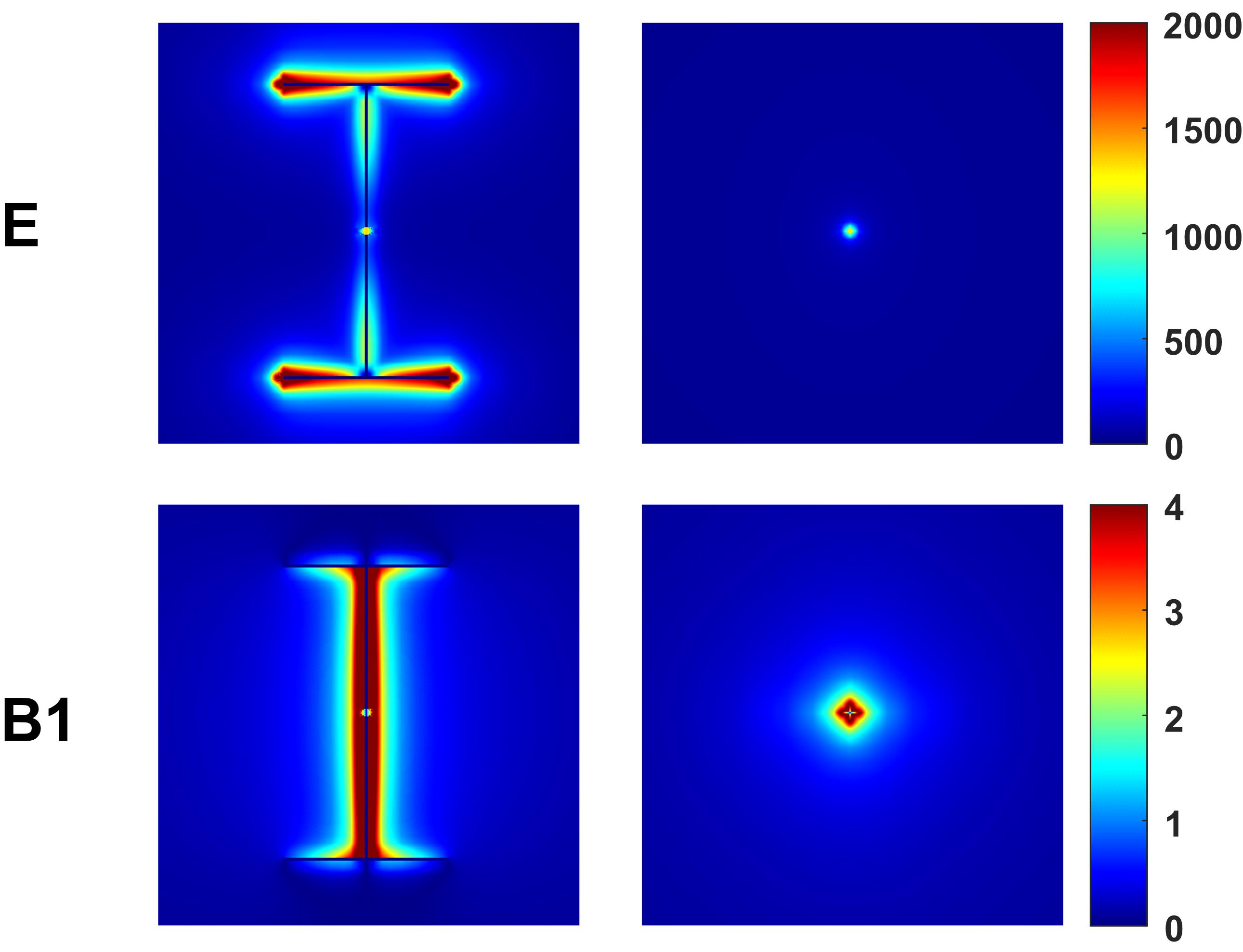
Figure2. The electric
and B1 map of H-shaped dipole antenna
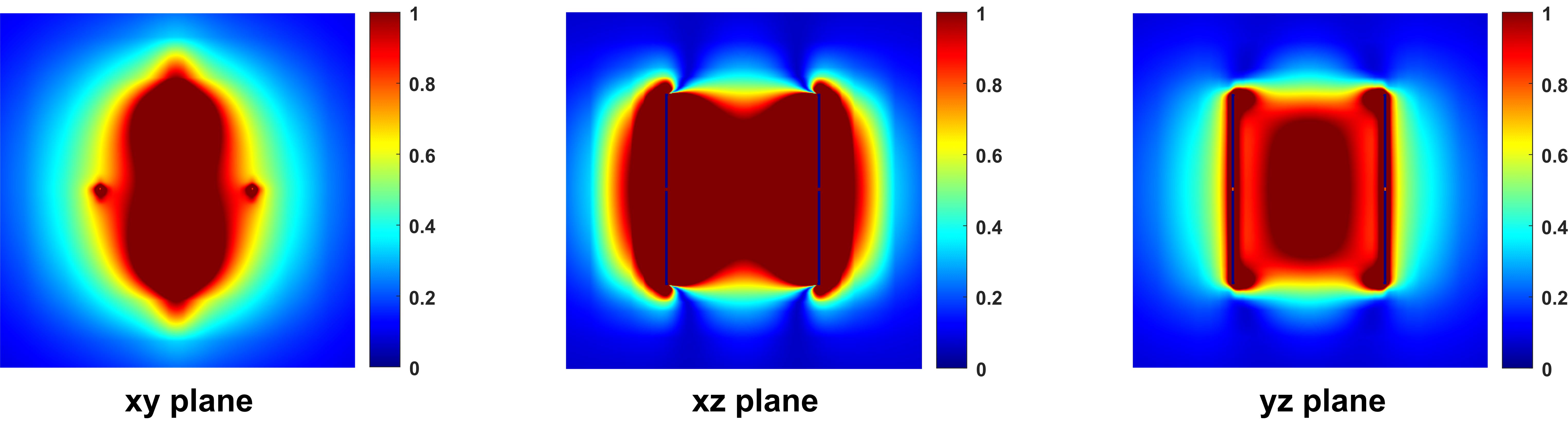
Figure3. The 400MHz B1
field of the volume RF coils with 4 H-shaped dipole antennas in xy, xz, yz
planes driven from one port
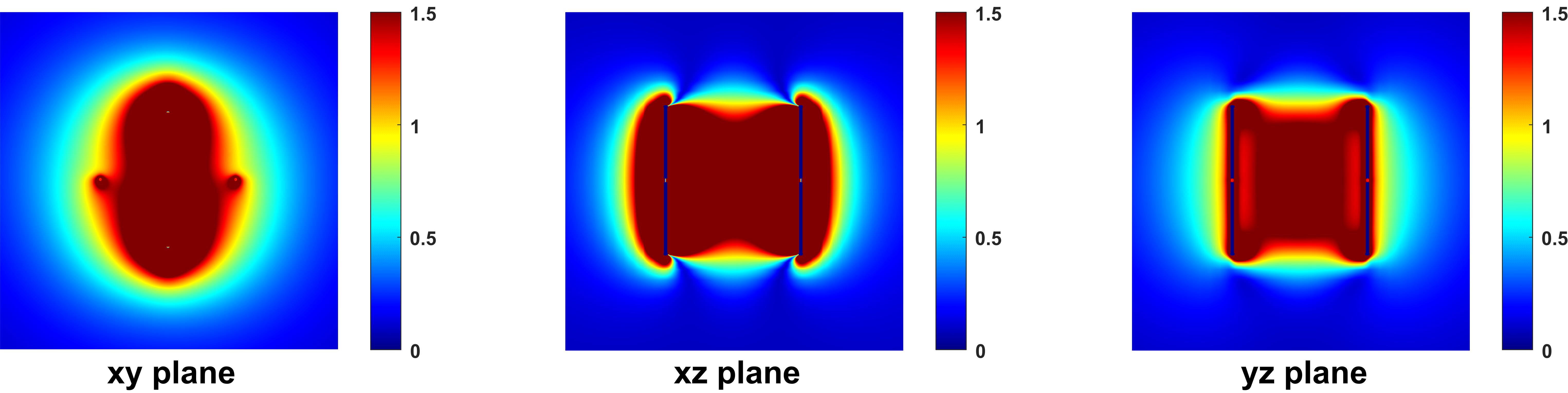
Figure4. The 600MHz B1
field of the volume RF coils with 4 H-shaped dipole antenna in xy, xz, yz
planes driven from one port
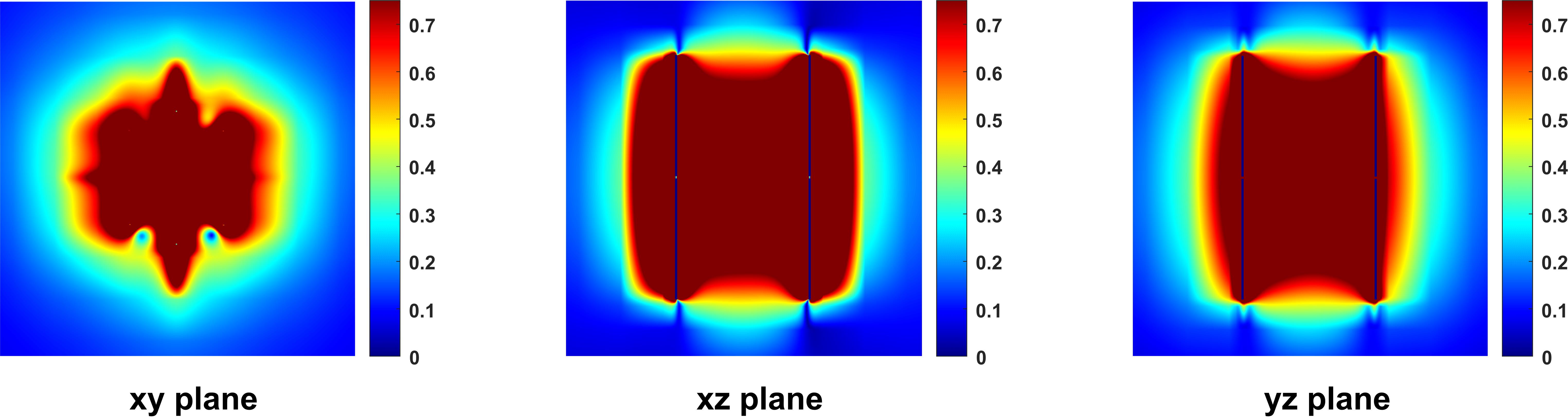
Figure5. The 400MHz B1 field of the volume RF coils with 8 H-shaped dipole antennas in xy, xz, yz planes driven from one port